Closed-Loop Bidirectional Brain-Computer Interfaces: System Design, AI Integration, and Clinical Translation
This article provides a comprehensive analysis of closed-loop bidirectional Brain-Computer Interface (bBCI) systems, which establish a direct communication pathway between the brain and external devices by both reading neural signals...
Closed-Loop Bidirectional Brain-Computer Interfaces: System Design, AI Integration, and Clinical Translation
Abstract
This article provides a comprehensive analysis of closed-loop bidirectional Brain-Computer Interface (bBCI) systems, which establish a direct communication pathway between the brain and external devices by both reading neural signals and writing sensory feedback. Tailored for researchers, scientists, and drug development professionals, it explores the foundational principles of bBCIs, detailing the system components and the critical role of artificial intelligence (AI) and machine learning (ML) in signal processing and adaptive control. The content covers methodological advances in invasive and non-invasive interfaces, applications in neurorehabilitation for conditions like Alzheimer's disease and paralysis, and the key challenges of biocompatibility, signal fidelity, and real-time processing. It further evaluates current clinical trials, commercial players, and validation metrics, concluding with a synthesis of future directions for integrating these systems into personalized biomedical and clinical research frameworks.
Bidirectional BCIs: Core Principles, System Architecture, and the AI-Driven Closed Loop
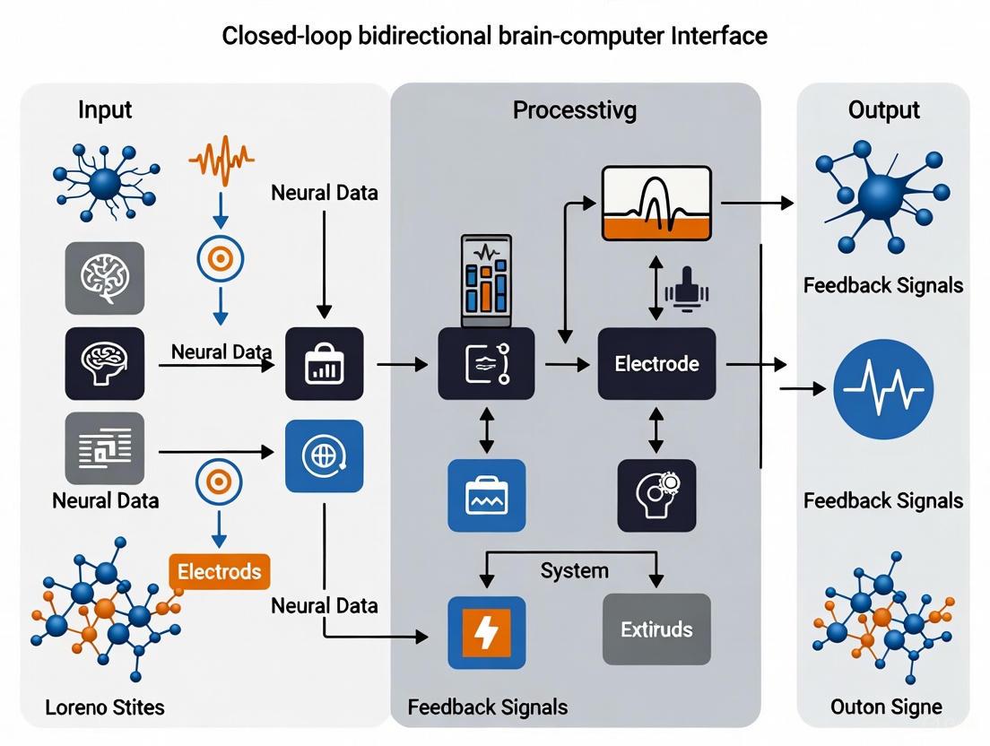
A Closed-Loop Bidirectional Brain-Computer Interface (BCI) represents a transformative neurotechnology that enables direct communication between the brain and external devices through two distinct pathways. It not only acquires and decodes neural signals to control external actuators but also writes information back into the nervous system through targeted stimulation, creating a continuous feedback loop [1]. This bidirectional flow of information fundamentally distinguishes it from earlier open-loop systems, allowing for adaptive, personalized interactions that more closely mimic natural neural processes.
The core operational pipeline of a closed-loop bidirectional BCI follows a structured sequence: (1) Signal Acquisition - measuring brain activity; (2) Processing - interpreting user intent from signals; (3) Output - executing commands on external devices; and (4) Feedback - providing sensory input back to the user, often through neural stimulation [2] [3]. This closed-loop design is the backbone of current BCI research, enabling real-time adjustment based on the brain's response to interventions [1]. The technological implementation of this pipeline requires careful balancing of multiple engineering and clinical considerations, particularly regarding the degree of invasiveness, signal fidelity, and long-term biocompatibility [2] [4].
System Architecture and Core Components
The Bidirectional Closed-Loop Paradigm
The architecture of a closed-loop bidirectional BCI system integrates multiple specialized components that work in concert to establish a continuous communication channel between the brain and an external device. Afferent pathways carry information from the brain to control external effectors, while efferent pathways carry information back to the nervous system, typically through electrical stimulation, to provide feedback or induce neuromodulation [5] [1]. This creates a continuous loop where the system adapts to the user's brain state while the user simultaneously learns to modulate their brain activity more effectively.
The following diagram illustrates the core architecture and information flow of a closed-loop bidirectional BCI system:
Signal Acquisition Modalities
Signal acquisition forms the critical first stage in the BCI pipeline, determining the quality and nature of information that can be extracted from neural activity. The field has developed a sophisticated two-dimensional framework for classifying acquisition technologies based on both surgical invasiveness and sensor operational location [2] [6]. This framework helps researchers balance trade-offs between signal quality, medical risk, and technical complexity when designing BCI systems.
Table 1: Two-Dimensional Classification of BCI Signal Acquisition Technologies
| Surgical Dimension (Clinical Perspective) | Detection Dimension (Engineering Perspective) | Example Technologies | Spatial Resolution | Temporal Resolution | Key Advantages | Key Limitations |
|---|---|---|---|---|---|---|
| Non-Invasive | Non-Implantation | EEG [2], MEG [7], fNIRS [7] | Low (cm) | High (ms for EEG/MEG) [7] | No surgical risk, suitable for mass adoption | Lower signal quality, vulnerability to artifacts |
| Minimal-Invasive | Intervention | Stentrode [1] | Medium (mm) | Medium (ms) | Reduced tissue damage, higher signal quality than non-invasive | Requires specialized surgical expertise |
| Invasive | Implantation | Microelectrode Arrays (e.g., Neuralink) [1], ECoG [7] | High (μm to mm) | High (ms) | Highest signal quality, direct neural recording | Highest surgical risk, tissue response, signal stability over time |
The surgical dimension addresses the degree of anatomical trauma caused during implementation, ranging from non-invasive (no trauma) to minimally invasive (trauma sparing brain tissue) to invasive (trauma affecting brain tissue) [2]. The detection dimension classifies technologies based on the sensor's operational location relative to the brain: non-implantation (on body surface), intervention (in natural body cavities), and implantation (within tissue) [2]. This comprehensive framework facilitates interdisciplinary collaboration between clinicians and engineers, which is essential for advancing BCI technology toward clinical applications [2].
Quantitative System Specifications
Performance Metrics for Bidirectional BCIs
Evaluating the performance of bidirectional BCI systems requires multiple quantitative metrics that capture both the information transfer capabilities and the efficiency of the system. For the afferent pathway (decoding), the Information Transfer Rate (ITR) measured in bits per second (bps) is a crucial metric that combines speed and accuracy of communication [8]. For the efferent pathway (stimulation), key parameters include stimulation current amplitude, pulse width, frequency, and charge balance to ensure tissue safety [5]. For implantable systems, power consumption becomes critically important, with recent advances achieving remarkably low power budgets of approximately 56 μW per channel for complete closed-loop systems [5].
Table 2: Quantitative Specifications of State-of-the-Art Bidirectional BCI Systems
| System Feature | Liu et al. (2017) [5] | Neuralink [1] | Paradromics [1] | Precision Neuroscience [1] |
|---|---|---|---|---|
| Recording Channels | 16 channels | >1000 electrodes | 421 electrodes (Connexus) | High-density surface array |
| Stimulation Channels | 16 programmable channels | Not specified | Not specified | Not specified |
| Stimulation Current | Up to 4 mA | Not specified | Not specified | Not specified |
| Stimulation Modes | Monopolar/bipolar, symmetrical/asymmetrical charge-balanced | Not specified | Not specified | Not specified |
| Power Consumption | 56 μW/channel | Not specified | Not specified | Not specified |
| Closed-Loop Control | In-channel programmable PID controllers | Yes | Yes | Yes |
| Key Innovation | Energy-efficient neural feature extraction | High-channel-count implant | Modular array with integrated wireless transmitter | Ultra-thin electrode array ("brain film") |
Hardware Implementation Considerations
The hardware implementation of bidirectional BCIs requires careful optimization of multiple competing parameters. There is an intriguing observed negative correlation between power consumption per channel (PpC) and Information Transfer Rate (ITR), suggesting that increasing channel counts can simultaneously reduce power consumption through hardware sharing while increasing information transfer by providing more input data [7]. This relationship highlights the importance of system-level optimization rather than focusing on individual components in isolation.
For practical deployment, especially in implantable systems, energy efficiency is paramount. Modern BCI chips fabricated in 0.18 μm CMOS technology have achieved complete system-on-chip (SoC) solutions integrating 16-channel neural recording front-ends, neural feature extraction units, 16-channel programmable neural stimulator back-ends, in-channel programmable closed-loop controllers, and analog-digital converters in a compact 3.7 mm² silicon area [5]. These hardware advances enable complex bidirectional interfaces while maintaining power budgets compatible with long-term implantation.
Experimental Protocols and Methodologies
Protocol 1: Sensory Input Paradigm (SSVEP-Based BCI)
Objective: To implement a steady-state visual evoked potential (SSVEP) based BCI for communication and control, particularly suitable for users with severe motor disabilities [8].
Materials and Setup:
- EEG Acquisition System: 64-channel EEG cap with wet electrodes, following the 10-20 international system [8].
- Visual Stimulator: 27-inch LED monitor with 60Hz refresh rate, displaying a 40-target QWERT virtual keyboard [8].
- Stimulation Protocol: Sampled sinusoidal stimulation method with frequencies ranging from 8-15.8 Hz [8].
- Signal Processing: Custom software for canonical correlation analysis (CCA) or ensemble methods for frequency recognition [8].
Procedure:
- Participant Preparation: Apply conductive EEG gel to achieve electrode impedances below 10 kΩ. Position participant 60 cm from visual stimulator.
- System Calibration: Present each visual target sequentially while recording EEG responses. Collect data across four blocks of trials.
- Feature Extraction: Apply filter-bank CCA to enhance signal-to-noise ratio of SSVEP responses.
- Closed-Loop Operation: Participants focus on desired characters while the system performs real-time classification of EEG signals.
- Performance Validation: Calculate information transfer rate (ITR) based on classification accuracy and selection speed.
Troubleshooting Tips:
- If signal quality is poor, check electrode impedances and reapplying gel if necessary.
- If classification accuracy is low, increase the number of calibration trials or optimize stimulus parameters.
Protocol 2: Motor Output Paradigm with Efferent Stimulation
Objective: To establish a closed-loop bidirectional interface for motor restoration, combining motor imagery decoding with sensory feedback through electrical stimulation.
Materials and Setup:
- Neural Recording System: 16-channel custom integrated circuit with action potential and local field potential recording capabilities [5].
- Stimulation System: Programmable current-mode stimulator with charge-balanced waveforms for tissue safety [5].
- Closed-Loop Controller: Proportional-Integral-Derivative (PID) controller implemented in hardware for real-time operation [5].
Procedure:
- System Configuration: Program stimulation parameters (amplitude, pulse width, frequency) for monopolar or bipolar symmetrical stimulation.
- Motor Imagery Training: Train participants to imagine specific motor acts (e.g., hand grasping) while recording from motor cortex.
- Decoder Calibration: Apply machine learning algorithms (e.g., support vector machines) to classify intended movements from neural patterns.
- Closed-Loop Integration: Link decoded motor commands to functional electrical stimulation (FES) devices or robotic actuators.
- Afferent Feedback: Provide sensory feedback through intracortical microstimulation (ICMS) or peripheral nerve stimulation.
Data Analysis:
- Calculate motor decoding accuracy across multiple trials.
- Quantify closed-loop performance using metrics like task completion time and success rate.
- Assess sensory discrimination performance through psychophysical testing.
The following diagram illustrates the experimental workflow for implementing and validating a closed-loop bidirectional BCI system:
Research Reagent Solutions and Materials
Table 3: Essential Research Reagents and Materials for Bidirectional BCI Implementation
| Item Name | Specifications | Function/Purpose | Example Application |
|---|---|---|---|
| Utah Array | 96-128 electrodes, spiked structure | Intracortical neural recording | High-resolution motor decoding studies [1] |
| Neuropixels | High-density CMOS probes | Large-scale neural activity mapping | Simultaneous recording from multiple brain regions |
| Stentrode | Endovascular electrode array | Minimally invasive signal acquisition | Motor decoding without open brain surgery [1] |
| Flexible ECoG Array | Ultra-thin conformable electrodes | Cortical surface recording | High-fidelity recording with minimal tissue damage [1] |
| CMOS BCI SoC | 0.18μm process, 16-channels, integrated ADC | Low-power neural signal processing | Portable/wearable closed-loop BCI systems [5] |
| Programmable Stimulator | Current-controlled, charge-balanced output | Safe neural stimulation | Sensory feedback in bidirectional BCIs [5] |
| PID Controller IC | Hardware-implemented control algorithm | Real-time closed-loop control | Adaptive stimulation based on neural state [5] |
Closed-loop bidirectional BCIs represent a paradigm shift in neurotechnology, moving beyond simple one-directional communication to establish rich, adaptive interfaces between brains and machines. The integration of high-fidelity signal acquisition with precisely targeted neural stimulation creates systems that can both interpret intent and restore sensation, offering unprecedented opportunities for therapeutic interventions in neurological disorders [4].
As of 2025, the field is transitioning from laboratory demonstrations to early clinical applications, with several companies including Neuralink, Synchron, Blackrock Neurotech, Paradromics, and Precision Neuroscience advancing human trials [1]. The trajectory suggests that bidirectional BCIs will follow a similar path to other transformative medical technologies, progressing from experimental prototypes to approved clinical tools as safety and efficacy are established in broader patient populations. Future developments will likely focus on improving biocompatibility, increasing channel counts while reducing power consumption, and developing more sophisticated adaptive algorithms that can learn and evolve with the user's changing neural patterns over time.
A bidirectional Brain-Computer Interface (bBCI) represents a significant evolution in neurotechnology, creating a closed-loop system that enables not only the decoding of neural signals to control external devices but also the encoding of sensory information back into the nervous system [9]. This direct communication pathway between the brain and an external device establishes a continuous feedback cycle, allowing for real-time monitoring and intervention [9]. Unlike traditional BCIs, which primarily facilitate one-way communication from the brain to an external device, bBCIs complete the loop by providing perceptible feedback to the user, which is crucial for neurorehabilitation and restoring sensory-motor functions [9]. The architecture of such systems is built upon four sequential, interdependent components that work in concert to translate intent into action and sensation into perception.
The Four Sequential Components of a bBCI System
The functional pipeline of a bBCI can be deconstructed into four core components: Signal Acquisition, Feature Extraction, Feature Translation, and Device Output & Feedback [9]. This closed-loop design—acquire, decode, execute, and feedback—forms the backbone of current BCI research [1]. The following diagram illustrates the workflow and the critical data flow between these components.
Component 1: Signal Acquisition
The initial stage of the bBCI pipeline involves measuring electrical activity from the brain. The methodology and physical location of this measurement are primary differentiators among modern neurotechnologies, presenting a trade-off between signal fidelity and invasiveness [1].
- Invasive Methods: These involve surgical implantation of microelectrode arrays directly onto or into the cerebral cortex to record from individual neurons or local field potentials. For example, the Utah array, a bed-of-nails style implant, has been a long-standing tool in BCI research [10] [1]. Newer, less invasive approaches are also emerging, such as Precision Neuroscience's Layer 7 Cortical Interface, a flexible electrode array that sits on the brain's surface and is implanted through a tiny slit in the skull [10] [1].
- Minimally Invasive Methods: Synchron's Stentrode is a prominent example, delivered via blood vessels through a catheter in the jugular vein. It lodges in a vein near the motor cortex, recording brain signals through the vessel wall without the need for open-brain surgery [1].
- Non-Invasive Methods: Techniques like Electroencephalography (EEG) use electrodes placed on the scalp. While safe and accessible, they measure the averaged activity of large populations of neurons, resulting in a lower signal-to-noise ratio (SNR) and spatial resolution compared to invasive methods [9].
Table 1: Comparative Analysis of Signal Acquisition Technologies
| Technology/Company | Acquisition Method | Invasiveness | Key Advantage | Reported Signal Fidelity |
|---|---|---|---|---|
| Utah Array [1] | Intracortical microelectrodes | Invasive | High-bandwidth single-neuron recording | Standard in foundational research |
| Neuralink [1] | Intracortical threads (1,024+ electrodes) | Invasive | Ultra-high channel count | Enables complex control tasks |
| Precision Neuroscience [10] [1] | Surface ECoG array (1,024 electrodes) | Minimally Invasive | High-resolution without tissue penetration | High-fidelity cortical surface signals |
| Synchron [1] | Endovascular stent electrode | Minimally Invasive | No open-brain surgery; delivered via blood vessels | Sufficient for computer control, texting |
| Research EEG [9] | Scalp electrodes | Non-Invasive | High safety and accessibility | Low spatial resolution, susceptible to noise |
Component 2: Feature Extraction
Once raw neural signals are acquired, the second component involves processing them to isolate and identify meaningful patterns or features that correspond to the user's intent. This step is critical for distinguishing relevant brain activity from noise and artifacts. The process typically involves sophisticated signal processing and, increasingly, machine learning algorithms [9].
Experimental Protocol: Feature Extraction from Motor Cortex Signals
- Objective: To extract discriminative features from motor cortex activity associated with attempted hand movements in a participant with paralysis.
- Materials:
- Implanted microelectrode array (e.g., Blackrock Neurotech Utah Array [1] or similar).
- High-sample-rate neural signal amplifier and data acquisition system.
- Computing platform with signal processing software (e.g., MATLAB, Python with SciPy/NumPy).
- Visual cueing system for task presentation.
- Methodology:
- Data Collection & Paradigm: The participant is shown a visual cue instructing them to attempt a specific hand movement (e.g., open hand, close hand). This trial is repeated dozens of times for each movement type.
- Pre-processing: The raw neural data is first filtered. A high-pass filter (e.g., 0.5-1 Hz cutoff) removes slow drifts, and a notch filter (e.g., 60 Hz) removes line noise. For action potential (spike) analysis, the data is also band-pass filtered (e.g., 300-5000 Hz) [11].
- Feature Calculation: The following features are computed for each trial within a predefined time window after the cue:
- Band Power: The power of the signal in specific frequency bands (e.g., Mu rhythm: 8-12 Hz, Beta rhythm: 13-30 Hz) is calculated using a method like the Welch periodogram.
- Firing Rates: For spike-sorted data, the average firing rate of individual neurons or groups of neurons is computed.
- Local Field Potential (LFP) Amplitude: The amplitude of the lower-frequency LFP signal can be extracted.
- Output: A feature vector for each trial, which can then be used to train a classifier in the next component.
Component 3: Feature Translation
In this stage, the extracted features are converted into commands for an external device. This is often described as the "decoding" step and relies heavily on machine learning (ML) and artificial intelligence (AI) models to map neural patterns to intended outputs [9]. The translation algorithm must be robust to the non-stationary nature of neural signals and adapt to the user's learning process.
Table 2: Machine Learning Algorithms for Feature Translation in bBCIs
| Algorithm | Primary Function | Application in bBCI | Key Consideration |
|---|---|---|---|
| Support Vector Machine (SVM) [9] | Classification | Discriminating between discrete movement intentions (e.g., left vs. right hand) [9]. | Effective for well-separated neural patterns; less suited for continuous control. |
| Convolutional Neural Network (CNN) [9] | Feature Learning & Classification | Decoding spectro-temporal patterns from neural data, such as identifying phonemes for speech BCIs [11]. | Requires large datasets; excels at finding spatial hierarchies in data. |
| Recurrent Neural Network (RNN/LSTM) | Time-Series Prediction | Decoding continuous trajectories (e.g., cursor movement) or sequences (e.g., sentences) from streaming neural data. | Handles temporal dependencies well; can be computationally intensive. |
| Transfer Learning (TL) [9] | Model Adaptation | Reducing calibration time by transferring knowledge from previous subjects or sessions to a new user. | Addresses high inter-subject variability, a key challenge in BCI [9]. |
Experimental Protocol: Training a Speech Decoder
- Objective: To train a translation algorithm that converts neural signals from the speech motor cortex into text.
- Materials:
- Methodology:
- Data Collection: The participant is asked to attempt to speak or silently imagine speaking a large set of words and sentences while neural data is recorded. The ground truth (the text they intended to say) is known to the experimenters.
- Alignment: The recorded neural data is carefully aligned word-by-word and phoneme-by-phoneme with the intended speech [11].
- Model Training: A deep learning model, such as a CNN or RNN, is trained on this aligned dataset. The model learns to map specific patterns of neural activity (the input features) to the corresponding linguistic units (the output text).
- Validation: The model's performance is tested on a held-out dataset not used during training. Accuracy is measured by the word error rate or phoneme error rate of the decoded speech. State-of-the-art systems have achieved up to 97% accuracy for discrete sentences [12].
- Output: A trained model that can, in real-time, take a stream of neural features as input and output a stream of text.
Component 4: Device Output & Feedback
The final component in the forward path of the bBCI loop is the execution of the decoded command by an external device. For the system to be bidirectional and closed-loop, this step must also include a mechanism for the user to perceive the result of their action, allowing them to correct errors and refine their mental commands [1] [9].
- Output Devices: The output can control a wide array of assistive technologies. This includes moving a computer cursor to type, operating a robotic arm or prosthetic limb, or driving a powered wheelchair [10] [1]. In speech neuroprosthetics, the output is synthetic speech generated from the decoded text [12].
- Sensory Feedback: The "bidirectional" aspect is achieved by feeding information back to the user. This is often visual (e.g., watching the cursor move) or auditory (e.g., hearing the synthesized speech). The ultimate goal for advanced bBCIs is to provide somatosensory feedback by electrically stimulating the sensory cortex to create artificial sensations of touch or proprioception, effectively "encoding" information back into the brain to create a truly immersive loop [9].
The following diagram synthesizes the entire bBCI closed-loop system, integrating all four components with the critical bidirectional feedback path.
The Scientist's Toolkit: Key Research Reagent Solutions
The advancement of bBCI research relies on a suite of specialized hardware and software tools. The following table details essential materials and their functions as derived from current research and commercial platforms.
Table 3: Essential Research Reagents and Materials for bBCI Development
| Item / Technology | Category | Function in bBCI Research | Example Use-Case |
|---|---|---|---|
| Utah Array (Blackrock Neurotech) [1] | Signal Acquisition | Standardized intracortical microelectrode array for recording single-neuron activity. | Foundational platform for the BrainGate clinical trials [10] [1]. |
| Layer 7 Cortical Interface (Precision Neuroscience) [10] [1] | Signal Acquisition | Flexible, high-density electrode array placed on the cortical surface for minimally invasive signal recording. | Mapping brain activity during temporary surgical procedures for epilepsy or tumor resection [10]. |
| Stentrode (Synchron) [1] | Signal Acquisition | Endovascular electrode array delivered via blood vessels to record motor cortex signals without craniotomy. | Enabling paralyzed users to control personal devices for digital communication [1]. |
| Neuralink Implant [1] | Signal Acquisition | High-channel-count intracortical implant with ultra-fine threads, placed by a specialized robotic system. | Early-stage human trials for restoring computer control to individuals with paralysis [1]. |
| BrainGate2 Software [12] | Feature Translation | Open-source software platform and protocol for real-time neural signal processing and decoding. | Multi-site clinical trial framework for evaluating BCI performance and algorithms [12]. |
| Transfer Learning (TL) Models [9] | Feature Translation | Machine learning models that adapt to new users with minimal calibration by leveraging data from previous subjects. | Reducing the long calibration times that are a major limitation in BCI systems [9]. |
| Microelectrode Arrays for Stimulation | Feedback Encoding | Intracortical microelectrodes used for delivering controlled electrical stimulation to sensory cortex regions. | Providing artificial tactile feedback by stimulating sensory areas corresponding to a prosthetic limb [9]. |
The architecture of a bidirectional BCI is a meticulously engineered sequence of four components: Signal Acquisition, Feature Extraction, Feature Translation, and Device Output & Feedback. This pipeline creates a closed-loop system where the brain and machine continuously interact and adapt. Deconstructing this architecture is fundamental for researchers and developers aiming to push the boundaries of neurotechnology. Current progress, evidenced by high-accuracy speech decoding and minimally invasive implants, signals a transition from laboratory research to tangible clinical applications. However, the future of bBCIs hinges on overcoming persistent challenges in signal stability, neural decoding, and the seamless, safe integration of bidirectional information flow. The ongoing convergence of advanced electrode design, robust AI models, and a deeper understanding of neural coding will be pivotal in realizing the full potential of bBCIs to restore function and deepen our comprehension of the human brain.
The Role of AI and Machine Learning in Real-Time Signal Decoding and System Adaptation
Application Notes: AI-Enhanced Signal Processing in BCI Closed-Loop Systems
The integration of Artificial Intelligence (AI) and Machine Learning (ML) is revolutionizing the capabilities of closed-loop bidirectional Brain-Computer Interfaces (BCIs). These technologies enable the real-time interpretation of neural signals and adaptive system responses, forming a dynamic feedback circuit between the brain and an external device [13] [9]. This document details the applications and protocols for implementing AI-driven signal decoding and adaptation within BCI systems for a research context.
Core AI/ML Techniques for Neural Decoding
Advanced ML models are critical for transforming noisy, complex neural data into reliable control commands. The table below summarizes the key algorithms and their applications in BCI systems.
Table 1: Key Machine Learning Techniques in BCI Signal Decoding
| ML Technique | Primary Application in BCI | Key Advantage | Reported Performance |
|---|---|---|---|
| Convolutional Neural Networks (CNNs) [13] [9] | Feature extraction & classification of spatial-temporal neural patterns. | Automates feature learning from raw or pre-processed signals, reducing manual engineering. | Enhanced accuracy in monitoring cognitive states [13] [9]. |
| Support Vector Machines (SVMs) [13] [9] | Classification of neural signals into discrete intent categories (e.g., move left/right). | Effective in high-dimensional spaces, robust against overfitting. | Widely used for reliable classification in neurorehabilitation tasks [13] [9]. |
| Transfer Learning (TL) [13] [9] | Adapting pre-trained models to new users with minimal calibration. | Reduces lengthy calibration sessions by leveraging data from previous subjects. | Addresses high variability in brain signals between individuals [13] [9]. |
| Random Forests (RF) [14] | Prognosis of disease progression and survival analysis. | Handles mixed data types well and provides estimates of feature importance. | Testing R² of 0.524 for predicting ALS patient survival time [14]. |
| Custom Decoder Algorithms [15] | Translation of EEG signals into movement intentions for robotic control. | Paired with computer vision to infer user intent and complete tasks. | Participants completed tasks (e.g., moving blocks) significantly faster with AI assistance [15]. |
Quantitative Performance of Next-Generation BCIs
Recent advances in both invasive and non-invasive BCIs, supercharged by AI, have demonstrated significant improvements in performance metrics critical for real-world application.
Table 2: Performance Metrics of Contemporary AI-Enhanced BCI Systems
| BCI System / Feature | Interface Type | Key Metric | Quantitative Result |
|---|---|---|---|
| AI Co-pilot System (UCLA) [15] | Non-invasive (EEG) | Task Completion Time | Paralyzed participant completed a robotic arm task in ~6.5 minutes with AI vs. unable to complete without it. |
| Speech Decoding [1] | Invasive (Implant) | Accuracy & Latency | Words inferred from brain activity at 99% accuracy and <0.25 second latency. |
| Synchron Stentrode [16] [1] | Minimally Invasive (Endovascular) | Long-term Safety & Efficacy | In a four-patient trial, users controlled a computer for texting; after 12 months, no serious adverse events were reported. |
| Neuralink [1] | Invasive (Implant) | Human Trial Progress | As of 2025, five individuals with severe paralysis are using the device to control digital and physical devices. |
| High-Variability Challenge [13] [9] | Model Training | Calibration Need | BCI applications often require per-user recalibration due to high inter-subject variability in brain signals. |
Experimental Protocols
Protocol: AI-Assisted Motor Intent Decoding for Robotic Arm Control
This protocol outlines the methodology for a closed-loop BCI that uses an AI co-pilot to assist users in completing physical tasks, based on a validated study [15].
Objective: To enable participants, including those with paralysis, to control a robotic arm to move objects using a non-invasive BCI augmented with a vision-based AI.
Materials:
- Signal Acquisition: EEG head cap with multiple electrodes.
- Data Processing Unit: Computer with custom decoder algorithms.
- AI Co-pilot System: Camera and software platform for real-time interpretation of the environment and user intent.
- Output Device: Robotic arm and a table with blocks.
- Software: Custom software for signal processing, AI inference, and device control.
Procedure:
- System Setup & Calibration:
- Fit the EEG cap on the participant. Ensure good electrode contact for signal quality.
- The participant is asked to imagine specific arm and hand movements (e.g., reach, grasp).
- Record EEG signals during these motor imagery tasks to train the user-specific decoder model.
- Task Initialization:
- Position four blocks on a table in predefined starting positions. The target positions for the blocks are programmed into the system.
- The AI co-pilot system is activated, using its camera to identify the blocks and their spatial context.
- Closed-Loop Operation:
- The participant is instructed to mentally intend to move a specific block to its target.
- Signal Acquisition: The EEG cap continuously records brain activity.
- Feature Extraction & Decoding: The custom decoder algorithms process the EEG signals in real-time to extract features reflecting movement intention and translate them into preliminary commands for the robotic arm.
- AI Inference: The camera-based AI observes the scene and the decoded movements. It infers the user's overarching goal (e.g., "move the red block to the left") and refines the raw commands for precision and task completion.
- Device Output: The refined commands are sent to the robotic arm, which executes the action of picking up and moving the block.
- Feedback: The participant observes the movement of the robotic arm, providing visual feedback to adjust their mental strategy for the subsequent command.
- Data Collection:
- Record the time taken to complete the task of moving all four blocks.
- Record success rate and any metrics on movement smoothness or precision.
- Validation:
- Compare task completion times and success rates with and without the AI co-pilot assistance [15].
Protocol: Decoding Internal Dialogue from Posterior Parietal Cortex
This protocol describes a method for capturing speech-related intentions from brain regions outside the primary motor cortex, enabling the decoding of internal dialogue.
Objective: To decode a limited vocabulary of internal, unspoken words from neural signals recorded in the posterior parietal cortex (PPC) [16].
Materials:
- Signal Acquisition: Implanted BCI in the posterior parietal cortex (e.g., dual-implant system as in Andersen's trials) [16].
- Neural Signal Recorder: High-fidelity system for capturing spiking activity and local field potentials.
- Computing System: High-performance computer with advanced deep learning models for sequence-to-sequence decoding.
- Stimulus Presentation Software: To cue the participant.
Procedure:
- Participant Training:
- The participant is presented with a set of target words or phrases on a screen.
- They are instructed to internally "say" or "think" the word without any overt movement or vocalization.
- Data Collection for Model Training:
- Simultaneously, neural activity from the PPC is recorded while the participant performs the internal speech task.
- This process is repeated hundreds of times for each word in the vocabulary to build a robust dataset pairing neural patterns with specific words.
- Model Training:
- A deep learning model (e.g., a recurrent neural network or transformer-based architecture) is trained on the collected data to map sequences of neural activity to the corresponding words.
- Closed-Loop Decoding:
- Cue: The participant is cued to think of a specific word from the trained set.
- Acquisition & Decoding: The BCI records PPC activity in real-time, and the trained model generates a probability distribution over the vocabulary.
- Output: The word with the highest probability is selected and converted into synthetic speech or displayed as text.
- Feedback: The participant hears the synthesized word or sees the text, allowing them to confirm or correct the output, thereby closing the loop and providing data to fine-tune the model.
Visualization of System Workflows
BCI Closed-Loop Workflow
Neuroadaptive AI Feedback Loop
The Scientist's Toolkit: Research Reagent Solutions
Table 3: Essential Materials and Reagents for BCI Experimentation
| Item Name | Function / Application | Specifications / Notes |
|---|---|---|
| High-Density EEG System [17] | Non-invasive recording of brain's electrical activity from the scalp. | Look for systems with high signal-to-noise ratio, multiple channels, and compatibility with real-time processing software. |
| Implantable Microelectrode Arrays (e.g., Utah Array, Neuralace) [1] | Invasive, high-fidelity recording from populations of neurons. | Provides superior spatial and temporal resolution compared to EEG. Key for decoding complex intent [16] [1]. |
| Endovascular Stentrode (Synchron) [1] | Minimally invasive recording via blood vessels; balances signal quality and safety. | Implanted in superior sagittal sinus; suitable for long-term chronic use without open-brain surgery [1]. |
| Custom Decoder Algorithms [15] | Core software for translating neural features into device commands. | Often developed in Python (Libraries: PyTorch, TensorFlow, Scikit-learn). Implement CNNs, SVMs, or RNNs based on the task [13] [15]. |
| AI Co-pilot Software [15] | Computer vision system that provides contextual awareness to assist the BCI decoder. | Interprets the user's environment (e.g., object location) to refine raw motor commands for successful task completion. |
| Robotic Arm / Output Device [15] | The physical actuator controlled by the BCI output. | Should have a programmable API for receiving commands from the BCI software. Crucial for neurorehabilitation and assistive applications. |
| Signal Processing Pipeline [17] | Software for filtering, artifact removal, and feature extraction from raw neural data. | Essential for handling noisy EEG signals. Steps include bandpass filtering, notch filtering, and Independent Component Analysis (ICA). |
Brain-Computer Interface (BCI) technology has emerged as a transformative tool in neuroengineering, establishing direct communication pathways between the brain and external devices [18]. For researchers and clinicians developing closed-loop bidirectional systems, the selection of neural interface type represents a fundamental design decision balancing signal fidelity against surgical risk and implementation complexity. This trade-off analysis is particularly critical in therapeutic applications where system performance directly impacts clinical outcomes.
Current BCI technologies are broadly categorized into three architectural approaches based on their level of invasiveness: non-invasive systems operating entirely externally, invasive devices implanted directly into brain tissue, and semi-invasive interfaces occupying an intermediate position within the skull but not penetrating neural tissue [18]. Each approach offers distinct advantages and limitations across key parameters including spatial resolution, temporal resolution, signal-to-noise ratio, and clinical risk profile.
The evolution toward bidirectional closed-loop systems has further intensified the need for precise interface selection, as these systems require both accurate readout of neural intent and effective write-in of therapeutic feedback [18] [19]. This analysis provides a structured framework for evaluating interface technologies within this specific context, supported by quantitative performance data and standardized experimental protocols.
Comparative Analysis of BCI Modalities
Performance and Characteristics
Table 1: Quantitative Comparison of BCI Interface Technologies
| Parameter | Non-Invasive (EEG) | Semi-Invasive (ECoG) | Invasive (Utah Array) |
|---|---|---|---|
| Spatial Resolution | 10-20 mm [18] | 1-10 mm [18] | 50-400 μm [1] |
| Temporal Resolution | ~100 ms [18] | <10 ms [18] | <1 ms [1] |
| Signal-to-Noise Ratio | Low (subject to noise) [9] | Moderate [18] | High (single-neuron recording) [20] |
| Signal Bandwidth | Low-frequency oscillations (<100 Hz) [18] | Broadband (0-500 Hz) [18] | Full-spectrum (0-7 kHz) [1] |
| Typical Channel Count | 64-256 channels [21] | 32-128 channels [18] | 100-1000+ channels [1] |
| Information Transfer Rate | 5-25 bits/min [22] | 20-50 bits/min [22] | Up to 100+ bits/min (speech decoding) [1] |
| Surgical Risk Profile | None [18] | Moderate (craniotomy required) [18] | High (brain penetration) [18] |
| Longevity/Stability | Unlimited [23] | Months to years [18] | Years (with potential signal degradation) [1] |
| Tissue Response | None | Mild gliosis [18] | Foreign body response, glial scarring [1] |
Technology Selection Guidelines
Table 2: Application-Based Interface Selection Matrix
| Research or Clinical Goal | Recommended Interface | Rationale | Key Limitations |
|---|---|---|---|
| Basic Motor Control (e.g., cursor, wheelchair) | Non-invasive (EEG) or Semi-invasive (ECoG) | Sufficient signal quality with minimized risk [23] [18] | Limited dexterity for complex tasks [23] |
| High-Performance Communication (e.g., speech decoding) | Invasive (microelectrode arrays) | Maximum signal fidelity required for phonetic discrimination [1] | Surgical risk, signal stability over time [1] |
| Long-Term Neuroprosthetics (e.g., robotic arm control) | Semi-invasive (ECoG) or Invasive | Balanced approach for sustained operation [18] | Biocompatibility and encapsulation [18] |
| Therapeutic Neurostimulation (e.g., epilepsy, depression) | Semi-invasive (responsive neurostimulation) | Targeted intervention with reduced infection risk [24] [18] | Limited spatial specificity compared to invasive [18] |
| Cognitive State Monitoring | Non-invasive (EEG/fNIRS) | Ample data for population-level algorithms [9] [23] | Individual calibration requirements [9] |
| Fundamental Neuroscience Research | Invasive (high-density arrays) | Single-neuron resolution for circuit analysis [1] [20] | Tissue damage potentially alters native physiology [18] |
Experimental Protocols for BCI Interface Evaluation
Protocol 1: Non-Invasive EEG System for Closed-Loop Motor Imagery
Objective: To establish a standardized methodology for implementing and validating a closed-loop motor imagery BCI using electroencephalography (EEG) for basic device control.
Materials:
- High-density EEG system (64+ channels with active electrodes)
- EEG amplification and acquisition system (minimum 24-bit resolution, 1000 Hz sampling rate)
- Electroconductive gel or saline solution
- Visual feedback display system
- BCI2000 or OpenVibe software platform
Procedure:
- Subject Preparation: Apply conductive gel to EEG electrodes according to 10-10 international system. Maintain electrode impedance below 5 kΩ throughout recording.
- Paradigm Design: Implement a cue-based motor imagery task with randomized trials for left hand, right hand, and foot movements.
- Signal Acquisition: Record EEG data at 1000 Hz sampling rate with appropriate referencing (e.g., common average or linked mastoids).
- Preprocessing: Apply 0.5-60 Hz bandpass filter and 50/60 Hz notch filter. Remove artifacts using independent component analysis (ICA).
- Feature Extraction: Calculate event-related desynchronization/synchronization (ERD/ERS) in mu (8-12 Hz) and beta (18-26 Hz) rhythms over sensorimotor cortex.
- Classification: Train support vector machine (SVM) or linear discriminant analysis (LDA) classifier on labeled training data (minimum 80 trials per class).
- Closed-Loop Implementation: Provide real-time visual feedback of classification output with update rate of 100-200 ms.
- Performance Validation: Assess using information transfer rate (bits/min) and classification accuracy across multiple sessions.
Validation Metrics: Information transfer rate >15 bits/min; Classification accuracy >75% for 3-class problem; Trial-to-trial consistency >80% [9] [22].
Protocol 2: Semi-Invasive ECoG Array Implantation and Recording
Objective: To define surgical and experimental procedures for obtaining stable cortical signals using electrocorticography (ECoG) arrays in bidirectional BCI applications.
Materials:
- Clinical-grade ECoG grid or strip electrodes (4 mm diameter, 10 mm inter-electrode distance)
- Sterile surgical instrumentation for craniotomy
- Neuromavigation system (e.g., StealthStation)
- Clinical EEG monitoring system with high-input impedance amplifiers
- Biocompatible cranial closure materials
Procedure:
- Surgical Planning: Preoperative MRI with fiducial markers for navigation. Identify target cortex (e.g., hand knob area for motor tasks).
- Craniotomy: Perform under general anesthesia with strict aseptic technique. Size opening to accommodate electrode array without folding.
- Array Placement: Position ECoG grid directly on pial surface over target region. Confirm placement with intraoperative photography and neuromavigation.
- Closure: Secure electrode cables to skull using titanium mini-plates. Close dura and soft tissues in layers.
- Postoperative Imaging: Obtain CT scan to confirm electrode locations. Co-register with preoperative MRI.
- Signal Acquisition: Begin recording after 24-48 hour stabilization period. Use 0.1-500 Hz bandpass with 2000 Hz sampling rate.
- Functional Localization: Conduct electrical cortical stimulation mapping to define eloquent areas.
- Task Paradigm: Implement motor execution and imagery tasks while recording ECoG signals.
- Signal Analysis: Extract high-gamma (70-150 Hz) power features using Hilbert transform with 500 ms sliding window.
- Bidirectional Operation: For closed-loop applications, integrate with neurostimulation capability for cortical perturbation.
Validation Metrics: Signal-to-noise ratio >20 dB; Stable high-gamma modulation across sessions; Successful identification of functional regions; Absidence of significant adverse events at 30-day follow-up [18] [22].
Protocol 3: Invasive Microelectrode Array Implementation for Precision Neuroprosthetics
Objective: To establish comprehensive procedures for implantation and validation of invasive microelectrode arrays for high-performance bidirectional BCI applications.
Materials:
- Utah array or Neuropixels probe
- Robotic insertion system or manual inserter
- Custom-designed titanium cranial chamber
- Protective headcap or pedestal
- High-channel-count neural recording system (256+ channels)
- Microstimulation-capable front end
Procedure:
- Preoperative Planning: High-resolution (3T) MRI and CT angiography to map vasculature and plan trajectory to target region.
- Surgical Approach: Perform craniotomy under general anesthesia with Mayfield head fixation. Utilize sterile technique throughout.
- Durotomy: Carefully incise dura to expose pial surface while preserving vascular integrity.
- Array Implantation: Using robotic inserter or manual insertion device, penetrate array into cortical tissue at predetermined location and depth.
- Securement: Affix array base to skull using medical-grade acrylic. Attach percutaneous connector or wireless transmitter.
- Closure: Close soft tissues around implantation site while protecting connector/transmitter.
- Postoperative Care: Administer antibiotics and monitor for infection. Obtain CT to confirm array placement.
- Neural Recording: Begin chronic recording after 1-2 week stabilization period. Use 0.3-7.5 kHz bandpass filtering with 30 kHz sampling rate.
- Spike Sorting: Apply automated spike sorting algorithms (e.g., Kilosort) to extract single-unit and multi-unit activity.
- Decoder Training: Implement recurrent neural network (RNN) or Kalman filter decoders for kinematic parameter estimation.
- Bidirectional Operation: Integrate microstimulation capability for sensory feedback with carefully controlled charge injection parameters.
Validation Metrics: Single-unit yield >100 units; Signal-to-noise ratio >4:1; Decoding accuracy >95% for direction and velocity; Stable recording duration >6 months; Minimal glial scarring on histology [1] [20].
The Scientist's Toolkit: Essential Research Reagents and Materials
Table 3: Critical Research Materials for BCI Interface Development
| Material/Reagent | Function | Specific Application Examples |
|---|---|---|
| Flexible Polymer Electrodes (e.g., polyimide, parylene-C substrates) | Minimize mechanical mismatch with neural tissue | Ultra-flexible neural interfaces reducing foreign body response [20] |
| Conductive Hydrogels | Improve electrode-tissue interface impedance | Chronic recording stability for semi-invasive interfaces [18] |
| Neural Growth Factors (e.g., NGF, BDNF) | Promote electrode integration | Surface modification to reduce glial scarring [18] |
| Anti-inflammatory Coatings (e.g., dexamethasone) | Mitigate foreign body response | Localized drug delivery from electrode surfaces [18] |
| Conductive Neural Adhesives | Secure electrode position while maintaining conductivity | Stable interface maintenance during micromotion [1] |
| Biocompatible Encapsulants (e.g., silicone, parylene) | Protect electronics from biological environment | Long-term implantation stability for invasive devices [1] |
| Quantum Dot Labels | Neural tracing and interface visualization | Post-mortem validation of electrode location and tissue response [22] |
| Calcium Indicators (e.g., GCaMP) | Optical validation of electrical recordings | Simultaneous electrophysiology and fluorescence imaging [22] |
System Architecture and Workflow Visualizations
The selection of appropriate neural interface technology represents a critical design decision in closed-loop bidirectional BCI systems, requiring careful balancing of signal fidelity requirements against surgical risk tolerance and long-term stability needs. As evidenced by the quantitative comparisons and standardized protocols presented herein, each interface modality occupies a distinct position within this trade-off space.
Non-invasive approaches provide the foundation for widespread BCI applications where minimal risk is paramount, while invasive technologies enable unprecedented neural decoding precision for the most challenging applications such as speech neuroprosthetics [1]. Semi-invasive interfaces continue to evolve as a strategic compromise, offering enhanced signal quality without penetrating brain parenchyma [18].
The ongoing development of flexible neural interfaces [20], advanced decoding algorithms [9] [22], and biocompatible materials is progressively reshaping these trade-offs, enabling higher performance with reduced risk. Future research directions should prioritize interface technologies that further optimize this fundamental balance, particularly through innovations that enhance long-term stability and functional integration while minimizing biological response.
Application Notes: Neurorehabilitation
Closed-loop Bidirectional Brain-Computer Interfaces (BCIs) are revolutionizing neurorehabilitation by creating direct pathways between neural activity and external devices, facilitating recovery through targeted neuroplasticity. These systems decode intention and provide contingent sensory feedback, forming an adaptive circuit for restoring function.
Stroke Motor Rehabilitation
BCI systems have demonstrated significant efficacy in post-stroke upper limb rehabilitation. A network meta-analysis of 13 studies directly compared the effectiveness of various interventions, with results summarized in the table below [25].
Table 1: Efficacy of BCI and Other Interventions on Upper Limb Function Recovery Post-Stroke (Fugl-Meyer Assessment Score)
| Intervention | Compared To | Mean Difference (MD) | 95% Confidence Interval | SUCRA Score (Ranking) |
|---|---|---|---|---|
| BCI-FES + tDCS | BCI-FES | 3.25 | [-1.05, 7.55] | 98.9% (1) |
| BCI-FES | Conventional Therapy | 6.01 | [2.19, 9.83] | 73.4% (2) |
| BCI-FES | FES alone | 3.85 | [2.17, 5.53] | - |
| BCI-FES | tDCS alone | 6.53 | [5.57, 7.48] | - |
| tDCS | - | - | - | 33.3% (3) |
| FES alone | - | - | - | 32.4% (4) |
| Conventional Therapy | - | - | - | 12.0% (5) |
The superior performance of combined BCI-FES and tDCS highlights the therapeutic advantage of multimodal approaches that synergistically promote neuroplasticity [25]. The closed-loop system reinforces the connection between motor intention and sensory feedback, which is crucial for recovery.
Experimental Protocol: BCI with Functional Electrical Stimulation (FES) for Upper Limb Rehabilitation
Objective: To improve upper limb motor function in chronic stroke patients using a closed-loop BCI-FES system. Primary Outcome Measure: Fugl-Meyer Assessment for Upper Extremity (FMA-UE) [25].
Materials:
- EEG acquisition system with active electrodes.
- Real-time signal processing unit (e.g., computer with BCI2000/OpenVibe).
- Functional Electrical Stimulator with surface electrodes.
- Visual feedback display.
Procedure:
- Patient Screening and Setup: Enroll patients meeting the inclusion criteria (e.g., adults >6 months post-stroke, Brunnstrom stage ≥ II). Place EEG electrodes over the primary motor cortex (C3, C4, Cz) and FES electrodes on the paretic forearm's extensor/flexor muscles.
- System Calibration:
- Instruct the patient to attempt or imagine a specific hand movement (e.g., opening/closing).
- Record EEG signals for 10-15 minutes to train a classifier (e.g., Support Vector Machine) to distinguish between "movement intention" and "rest" states.
- Therapy Session:
- The patient is cued to attempt the movement.
- The BCI system acquires EEG signals in real-time and processes them to extract features like Sensorimotor Rhythm (SMR) power.
- Upon detecting movement intention above a set threshold, the system automatically triggers the FES to elicit the actual movement.
- The patient receives simultaneous visual feedback on a screen, confirming the successful detection of their intention.
- A typical session lasts 60 minutes, conducted 3-5 times per week for 4-6 weeks.
- Adaptation: The detection threshold is adjusted weekly based on patient performance to maintain an optimal challenge level.
Rationale: This protocol closes the sensorimotor loop by linking endogenous motor commands with peripheral proprioceptive feedback from FES-induced movement, strengthening efferent-reafferent coupling and driving cortical reorganization [25] [26].
Diagram 1: Closed-Loop BCI-FES Rehabilitation Workflow
Application Notes: Cognitive Assessment and Neurological Disorders
BCIs offer a novel paradigm for the longitudinal monitoring and assessment of cognitive states, particularly in neurodegenerative diseases like Alzheimer's disease and related dementias (AD/ADRD) [13].
Cognitive State Monitoring
BCI systems can detect neurophysiological changes that precede noticeable cognitive decline. Machine learning (ML) algorithms are trained to classify EEG patterns correlated with specific cognitive states, such as memory load, attention, or the early signs of cognitive impairment [13]. Key ML techniques enhancing these systems include:
- Transfer Learning (TL): Mitigates the need for lengthy per-user calibration by adapting models from a pool of users.
- Convolutional Neural Networks (CNNs): Effectively extract spatial features from multi-channel EEG signals.
- Support Vector Machines (SVMs): Provide robust classification of cognitive states from extracted features [13].
These systems can be configured to provide real-time alerts to caregivers upon detecting signatures of significant cognitive events or declines, enabling proactive patient management [13].
Experimental Protocol: Longitudinal EEG Monitoring for Cognitive Assessment
Objective: To track cognitive state fluctuations in patients with AD/ADRD using a non-invasive BCI system. Primary Outcome: Cognitive state classification (e.g., normal, mild cognitive impairment, high cognitive load) [13].
Materials:
- Wearable EEG headset (e.g., 8-16 channels).
- Portable computing unit (e.g., tablet) for data processing.
- Cloud/server for longitudinal data storage and analysis.
Procedure:
- Baseline Establishment: Record resting-state EEG and event-related potentials (ERPs) during standardized cognitive tasks (e.g., auditory oddball) to establish an individual baseline.
- At-Home Monitoring: The patient uses a wearable EEG headset for prescribed periods (e.g., 30 minutes daily). The system records EEG during specific activities or at rest.
- Data Processing and Analysis:
- Preprocessing: Apply filters to remove artifacts (eye blinks, muscle noise).
- Feature Extraction: Compute relevant features (e.g., power spectral density in alpha, beta, theta bands; P300 amplitude/latency).
- State Classification: A pre-trained CNN or SVM model classifies the EEG epochs into predefined cognitive states.
- Alert System: If the system detects patterns consistent with a significant decline or a pre-defined event over multiple sessions, an automated summary report is sent to the clinician.
- Adaptation: The classification model is periodically updated (e.g., every month) using the accumulated longitudinal data to improve personalization.
Rationale: This protocol enables continuous, objective assessment in a real-world environment, capturing data that may be missed in sporadic clinical visits and facilitating earlier intervention [13].
Application Notes: Restoring Motor and Sensory Functions
Bidirectional BCIs not only decode motor intent to control external devices but also write information back to the brain by providing artificial sensory feedback, creating a more naturalistic and functional loop.
Advanced Motor and Sensory Restoration
Innovative approaches are pushing the boundaries of functional restoration:
- Motor Imagery Classification: Advanced deep learning models are achieving remarkable precision in decoding motor intent. Hierarchical architectures combining CNNs for spatial feature extraction, Long Short-Term Memory (LSTM) networks for temporal dynamics, and attention mechanisms for feature weighting have achieved classification accuracies exceeding 97% on four-class motor imagery tasks [27]. This high level of accuracy is critical for reliable control of neuroprosthetics.
- Organoid-BCI Interfaces (OBCIs): A groundbreaking approach for repairing major brain injuries involves implanting 3D brain organoids into damaged cavities. Flexible electrodes are implanted within the organoid and connected to the host brain. Electrical stimulation via the OBCI has been shown to promote graft differentiation, enhance synaptic density, and guide functional integration with the host neural circuitry, demonstrating potential for reconstructing damaged neural pathways [28].
Table 2: Key Performance Metrics in Modern BCI Applications
| Application | Metric | Reported Performance | Key Technology/Model |
|---|---|---|---|
| Motor Imagery Decoding | Classification Accuracy | >97% [27] | Attention-enhanced CNN-LSTM |
| Upper Limb Rehabilitation | FMA-UE Improvement vs. CT | MD: 6.01 points [25] | BCI-FES Closed-loop |
| Organoid Integration | Synaptic Density | Increased in stimulated grafts [28] | OBCI with flexible electrodes |
Experimental Protocol: Organoid-BCI (OBCI) for Brain Repair
Objective: To promote the structural and functional integration of implanted brain organoids with the host brain using electrical stimulation [28].
Materials:
- In-vitro differentiated brain organoids.
- Dual-shank flexible microelectrode arrays.
- Stereotaxic surgical setup.
- Programmable electrical stimulator.
Procedure:
- Organoid Preparation: Culture brain organoids for approximately 90 days in vitro to ensure sufficient neuronal maturation.
- Cavity Creation and Transplantation: Create a defined cavity in the primary sensory cortex (S1) of the animal model. Transplant the GFP-expressing organoid into the cavity.
- Electrode Implantation: At 25 days post-transplantation, perform a secondary procedure to implant a flexible electrode array. Under guidance, one shank is inserted into the transplanted organoid and another into an adjacent host brain region (e.g., primary motor cortex, M1).
- Closed-Loop Stimulation:
- Early-Stage Regulation (Weeks 1-4): Apply biphasic electrical stimulation (e.g., 50 Hz, 50 μA) to the organoid to promote neuronal differentiation and maturation.
- Late-Stage Regulation (Weeks 5+): Record neural activity from the host M1. Upon detecting specific activity patterns (e.g., related to a behavior), deliver timed stimulation to the organoid to strengthen functional connectivity.
- Outcome Assessment:
- Histology: Analyze graft differentiation (NeuN, TBR1, CTIP2), synaptic markers (Synapsin, PSD95), and axonal projections.
- Electrophysiology: Record cross-correlated activity between the organoid and host M1 to assess functional connectivity.
Rationale: Electrical stimulation promotes neuronal differentiation and guides targeted axonal outgrowth. Pairing host neural activity with organoid stimulation encourages the formation of task-relevant functional circuits, potentially restoring lost functions [28].
Diagram 2: Organoid-BCI Implantation and Stimulation Protocol
The Scientist's Toolkit: Research Reagent Solutions
Table 3: Essential Materials and Reagents for Closed-Loop BCI Research
| Item | Function/Application | Examples & Notes |
|---|---|---|
| Flexible Brain Electronic Sensors (FBES) | High-fidelity, biocompatible neural signal acquisition. Essential for chronic implants and OBCIs. | Flexible electrode arrays; reduce immune response and improve signal stability over rigid electrodes [28] [29]. |
| Signal Acquisition Systems | Recording electrical brain activity. | EEG systems (non-invasive); ECoG grids (semi-invasive); Microelectrode arrays (invasive) [26]. |
| Machine Learning Algorithms | Classifying intent/cognitive state from neural signals. | Support Vector Machines (SVM), Convolutional Neural Networks (CNN), Long Short-Term Memory (LSTM) networks, Transfer Learning [13] [27]. |
| Neuromodulation Devices | Providing feedback or stimulating neural tissue. | Functional Electrical Stimulators (FES), Transcranial Direct Current Stimulation (tDCS) devices, intracortical microstimulators [25] [30]. |
| Brain Organoids | 3D in-vitro models of brain tissue for repair strategies. | Human iPSC-derived organoids; used for transplantation and circuit repair in OBCI studies [28]. |
| Neuronal Cell Markers | Histological validation of neuronal differentiation and connectivity. | Antibodies for NeuN (mature neurons), Synapsin/PSD95 (synapses), TBR1/CTIP2 (cortical layers) [28]. |
Design and Implementation: From Flexible Neural Interfaces to Clinical Neuroprosthetics
Brain-computer interface (BCI) technology represents a groundbreaking domain within neuroengineering, facilitating direct communication between the brain and external devices [18]. The efficacy of BCI systems is largely contingent upon their signal acquisition module, which bears the critical responsibility for detecting and recording cerebral signals [2]. In closed-loop bidirectional system design, the choice of neural signal acquisition technique directly impacts system performance, feedback precision, and clinical applicability. This article provides detailed application notes and experimental protocols for four principal neural signal acquisition modalities—electroencephalography (EEG), electrocorticography (ECoG), intracortical microelectrodes, and endovascular stents—framed within the context of advanced BCI system research.
Technical Specifications and Comparative Analysis
Quantitative Comparison of Acquisition Techniques
Table 1: Comparative analysis of neural signal acquisition techniques for closed-loop bidirectional BCI systems
| Parameter | EEG | ECoG | Intracortical Microelectrodes | Endovascular Stents |
|---|---|---|---|---|
| Spatial Resolution | 1-3 cm [31] | 0.5-5 mm [31] | 50-100 μm [32] | 1-2.4 mm [31] |
| Temporal Resolution | ~100 Hz [31] | 0-500 Hz [32] | 0-7000 Hz [32] | Local field potentials (comparable to ECoG) [31] |
| Signal Amplitude | ~100 μV [31] | Microvolts (μV) range [32] | Millivolt (mV) range for action potentials [32] | Higher than EEG (closer to neural tissue) [31] |
| Invasiveness Level | Non-invasive [2] | Invasive (requires craniotomy) [31] | Highly invasive (penetrates brain tissue) [31] | Minimally invasive (via catheterization) [31] |
| Tissue Damage Risk | None | Lower risk; surface electrodes [32] | Higher risk; inflammatory response, glial scarring [32] | Minimal; uses natural blood vessels [2] |
| Long-term Stability | High (no implantation) | Stable long-term recordings [32] | Signal degradation over time possible [32] | Research ongoing; potential for stability |
| Surgical Procedure | Not applicable | Craniotomy required [32] | Burr hole or craniotomy [31] | Endovascular catheterization [31] |
| Clinical Translation Stage | Widely established | Established for epilepsy monitoring [31] | Research and severe paralysis cases [32] | Emerging clinical applications [31] |
Signal Characteristics and BCI Applications
Table 2: Signal characteristics and application suitability for bidirectional BCIs
| Characteristic | EEG | ECoG | Intracortical Microelectrodes | Endovascular Stents |
|---|---|---|---|---|
| Primary Signal Types | Averaged neuronal population activity [31] | Local field potentials [32] | Single-unit activity & local field potentials [32] | Local field potentials [31] |
| Frequency Range | 0-100 Hz [31] | 0-500 Hz [32] | 0-7000 Hz [32] | Comparable to ECoG [31] |
| Artifact Susceptibility | High (environmental noise) [18] | Less susceptible to motion artifacts [32] | Prone to signal degradation [32] | Less than EEG (internal placement) |
| Motor Control Applications | Basic control [18] | Gross movements (arm reaching) [32] | Fine dexterous control (individual fingers) [32] | Research phase |
| Sensory Feedback Capability | Limited | Basic tactile sensations [32] | Fine-grained proprioceptive feedback [32] | Potential for stimulation |
| Communication Applications | Spelling interfaces | Spelling interfaces [32] | Complex language production [32] | Research phase |
Experimental Protocols
Protocol: Non-invasive EEG Acquisition for Closed-Loop BCI
Objective: To acquire EEG signals for real-time closed-loop BCI control with sensory feedback.
Materials:
- High-density EEG system (64-128 channels) [31]
- Electrode caps with Ag/AgCl electrodes
- Conductive electrolyte gel
- Amplifier system with 0.1-100 Hz bandpass filter
- Visual or auditory stimulation setup
- Signal processing unit (PC with MATLAB/Python)
Procedure:
- Preparation: Clean scalp with abrasive gel to achieve impedance <5 kΩ. Position electrode cap according to 10-20 international system.
- Signal Acquisition: Configure amplifier settings (sampling rate: 256-512 Hz, resolution: 16-bit). Record resting-state baseline for 5 minutes with eyes open and closed.
- Paradigm Design:
- For motor imagery: Present visual cues for 4-second trials indicating left/right hand movement imagination.
- For evoked potentials: Present visual stimuli at 2-second intervals for P300 paradigms.
- Real-time Processing: Implement Common Average Reference (CAR) or Laplacian filter. Extract band power features (8-30 Hz) for motor imagery or temporal features for evoked potentials.
- Closed-loop Operation: Translate features to device commands. Provide visual feedback on performance. Adjust decoding algorithm parameters based on accuracy.
Quality Control: Monitor impedance throughout session. Reject artifacts using automated algorithms (threshold: ±100 μV). Maintain constant temperature and lighting.
Protocol: ECoG Electrode Implantation and Signal Acquisition
Objective: To implant ECoG electrodes and record high-resolution signals for bidirectional BCI applications.
Materials:
- Sterile ECoG electrode grid (e.g., 8×8 array with 4 mm contacts)
- Surgical instruments for craniotomy
- Navigation system (stereotactic frame or neuromavigation)
- Clinical EEG recording system
- Biocompatible securing materials
Procedure:
- Surgical Planning: Preoperative MRI for navigation. Mark craniotomy location over target cortex (e.g., sensorimotor area).
- Implantation: Perform craniotomy under general anesthesia. Place grid on cortical surface via durotomy. Ensure contact with pial surface.
- Validation: Confirm placement with intraoperative photography or fluoroscopy. Verify electrode impedance (<1 kΩ). Record cortical responses to direct electrical stimulation for functional mapping.
- Signal Acquisition: Record resting-state activity (5 minutes). Implement event-related paradigms (motor tasks, sensory stimulation). Use sampling rate of 1000-2000 Hz with 0.5-300 Hz bandpass filter.
- Closed-loop Configuration: Extract high-gamma band (70-150 Hz) power features. Map features to output commands for prosthetic control. Provide sensory feedback through electrical stimulation of cortex.
Post-procedure: Monitor for infection or complications. Record continuous data for several days to weeks for chronic applications.
Protocol: Intracortical Microelectrode Recording for High-Resolution BCI
Objective: To record single-unit and multi-unit activity for high-precision bidirectional BCI control.
Materials:
- Utah array or Michigan probe
- Sterile surgical equipment
- Microdrive system for precise placement
- High-impedance amplifiers (>1 MΩ)
- Neural signal processor
Procedure:
- Surgical Approach: Perform craniotomy under sterile conditions. Utilize stereotactic guidance for target localization.
- Electrode Placement: Slowly insert array into cortical tissue (e.g., primary motor cortex). Use micromanipulator to minimize tissue damage. Confirm depth via intraoperative imaging or functional responses.
- Signal Acquisition: Record broadband signal (0.1-7000 Hz). Sample at 30 kHz to capture action potential waveforms. Separate local field potentials (LFP: 0.1-300 Hz) and single-unit activity (300-7000 Hz).
- Spike Sorting: Apply bandpass filter (300-3000 Hz) for spike detection. Use principal component analysis for spike sorting. Isolate single units based on waveform characteristics.
- Bidirectional Operation: Decode intended movement from firing patterns of neuron ensembles. Deliver intracortical microstimulation (ICMS) for sensory feedback (parameters: 10-100 μA, 200 Hz, 100 ms pulse trains).
Chronic Recording: Monitor signal quality daily. Implement automated spike sorting validation. Apply antiseptic techniques to prevent infection.
Protocol: Endovascular Stent Electrode Implantation and Recording
Objective: To deploy endovascular stent electrodes and record neural signals without open brain surgery.
Materials:
- Stentrode or similar endovascular electrode array
- Angiographic suite with fluoroscopy
- Microcatheter delivery system
- Guidewires and introducer sheaths
- Biplanar digital subtraction angiography (DSA) capability
Procedure:
- Vascular Access: Insert introducer sheath into femoral artery. Administer heparin to prevent clotting.
- Navigation: Under fluoroscopic guidance, navigate microcatheter through aorta to target cerebral vessel (e.g., superior sagittal sinus).
- Deployment: Deploy self-expanding stent electrode against vessel wall. Confirm apposition with contrast injection.
- Signal Validation: Record spontaneous neural signals. Compare with simultaneous scalp EEG or ECoG if available. Perform functional localisation with movement or cognitive tasks.
- Chronic Recording: Connect to subcutaneous transmitter for continuous monitoring. Monitor signal stability over weeks to months.
Safety Considerations: Regular vascular imaging to assess patency. Antiplatelet therapy to prevent thrombosis. Signal monitoring for stability assessment.
Signaling Pathways and System Workflows
Diagram 1: Workflow for EEG-based closed-loop BCI system. The system creates a continuous loop where sensory feedback influences subsequent brain activity, enabling adaptive learning [9].
Diagram 2: Integrated bidirectional BCI system incorporating multiple acquisition modalities. This architecture enables both recording and stimulation capabilities essential for closed-loop operation [18].
The Scientist's Toolkit: Research Reagent Solutions
Table 3: Essential research reagents and materials for neural signal acquisition research
| Reagent/Material | Function/Application | Specifications |
|---|---|---|
| Ag/AgCl Electrodes | EEG signal transduction | 4-10 mm diameter; low impedance (<5 kΩ) [31] |
| Electrode Gel | Scalp interface for EEG | Conductive chloride-based; low viscosity |
| Utah Array | Intracortical recording | 96-microelectrode array; 1-1.5 mm length [31] |
| Michigan Probe | Laminar cortical recording | 16-64 contact sites; silicon substrate [31] |
| ECoG Grid | Subdural surface recording | Platinum-iridium contacts; 2-10 mm spacing [31] |
| Stentrode | Endovascular recording | Nitinol stent structure; electrode diameter 500-750 μm [31] |
| Neuropixels Probe | High-density recording | 960 recording sites; CMOS technology |
| PEDOT:PSS Coating | Electrode surface modification | Improves signal-to-noise ratio; reduces impedance |
| Bioplene Mesh | ECoG grid backing | Flexible; biocompatible substrate |
| Medical Grade Silicone | Implant encapsulation | Protects electronics; provides biocompatibility |
The selection of appropriate neural signal acquisition techniques is fundamental to successful closed-loop bidirectional BCI system design. Each modality offers distinct trade-offs between invasiveness, signal quality, and clinical applicability. EEG remains the most accessible non-invasive approach, while ECoG provides a balanced intermediate solution. Intracortical microelectrodes deliver the highest signal resolution but with increased biological risk, and endovascular stents represent a promising minimally invasive alternative with comparable signal quality to ECoG. Future developments in materials science, electrode design, and signal processing algorithms will further enhance the capabilities of these acquisition techniques, advancing the field of bidirectional BCIs for both fundamental research and clinical applications.
Electrical stimulation of the cortex, particularly Intracortical Microstimulation (ICMS), has emerged as a pivotal technique for restoring sensory function in closed-loop bidirectional brain-computer interfaces (BCIs). These systems aim to provide artificial sensory feedback by directly interfacing with neural tissue, enabling applications in sensory restoration and neuroprotection. Recent research has significantly advanced our understanding of how both neuronal and non-neuronal cells respond to electrical stimulation, revealing complex biological mechanisms that underlie the efficacy and limitations of these technologies. The cellular response to ICMS involves precisely orchestrated interactions between excitatory and inhibitory neuronal populations, glial cells, and the neurovascular unit [33] [34]. These responses are highly dependent on stimulation parameters including current amplitude, frequency patterns, and duration, which collectively determine both the functional outcomes and potential tissue reactions [35] [36]. A comprehensive understanding of these mechanisms is essential for designing safe and effective closed-loop BCI systems that can maintain stable sensory percepts over extended periods while minimizing unwanted tissue responses.
Key Biological Findings and Quantitative Data
Cellular and Vascular Responses to ICMS
Recent studies have revealed that ICMS triggers rapid cellular responses beyond merely activating neuronal pathways. Microglia, the brain's resident immune cells, demonstrate process convergence within 15 minutes of stimulation onset, with this response intensifying at higher current amplitudes [33] [35]. Concurrently, blood-brain barrier (BBB) integrity is affected, as evidenced by increased vascular dye penetration into brain tissue that similarly scales with current amplitude [33]. These findings highlight the importance of considering non-neuronal cell responses when establishing safety parameters for chronic ICMS applications.
Table 1: Cellular and Vascular Responses to Intracortical Microstimulation
| Response Type | Time Course | Amplitude Dependence | Functional Implications |
|---|---|---|---|
| Microglia Process Convergence | Within 15 minutes | Increases with higher current amplitudes | Potential neuroinflammatory response; requires monitoring in chronic implants |
| Blood-Brain Barrier Permeability | Acute (minutes) | Higher dye penetration at increased amplitudes | Potential risk factor; necessitates optimized safety protocols |
| Excitatory Neuron Activity | Millisecond to second scale | Preferentially activated by 10-Hz burst patterns | Primary drivers of sensory percepts; show activity fading |
| Inhibitory Neuron Activity | Millisecond to second scale | Preferentially activated by theta-burst stimulation | Regulate network dynamics; contribute to perceptual fading |
The dynamic balance between excitatory and inhibitory neuronal activity during ICMS plays a crucial role in shaping the resulting sensory percepts. Research in mouse visual cortex demonstrates that inhibitory neurons are more consistently activated across different stimulation patterns compared to excitatory neurons [34]. During prolonged ICMS (30-second duration), inhibitory neuron activity typically increases throughout the stimulation period, while excitatory neuron activity more frequently decreases and can be suppressed following stimulation offset [34]. Different stimulation patterns engage these neuronal populations differentially: theta-burst stimulation most effectively activates inhibitory neurons, whereas 10-Hz bursts most effectively activate excitatory neurons [34]. These differential response patterns have significant implications for managing perceptual fading during sustained sensory feedback in BCIs.
Sensory Percept Properties in Human Applications
In human clinical applications, ICMS of somatosensory cortex evokes tactile sensations that demonstrate remarkable stability over time. Research with spinal cord injury participants has shown that projected fields (PFs) remain stable over several years, with centroid distances showing no significant change over time in multiple participants [36]. These PFs typically comprise focal hotspots with diffuse borders, ranging in size from 0.3-11.3 cm² (median 2.5 cm²) across different hand regions [36]. The intensity of these percepts can be systematically modulated by stimulation parameters, with detection thresholds increasing slowly over time at approximately 3.5 μA per year [37]. After a decade of continuous implantation, 55% of electrodes still reliably evoke tactile sensations, demonstrating the potential for long-term sensory restoration [37].
Table 2: Properties of ICMS-Evoked Sensory Percepts in Human Applications
| Percept Property | Measurement/Range | Temporal Stability | Functional Utility |
|---|---|---|---|
| Projected Field Size | Median: 2.5 cm² (Range: 0.3-11.3 cm²) | Stable over years (centroid distance consistent) | Enables consistent mapping to bionic hand sensors |
| Detection Threshold | ~3.5 μA/year increase | Slow progression over years | 55% electrodes functional after 10 years |
| Spatial Coverage | 7-20% of total hand surface | Stable somatotopic organization | Determines portion of robotic hand providing feedback |
| Intensity Discrimination | Worse than natural touch (individual electrodes) | Improved via biomimetic temporal patterns | Enhanced via multi-electrode stimulation |
Multi-electrode stimulation approaches significantly enhance the functional utility of ICMS-evoked sensations. When electrodes with overlapping projected fields are stimulated simultaneously, the resulting percept resembles a summation of its components, becoming more focal and easier to localize [36]. This approach also produces a wider range of percept intensities, providing more discrete steps for conveying force information from bionic hands. Furthermore, adjusting the temporal structure of stimuli to mimic naturally evoked neural activity patterns (biomimicry) improves intensity discrimination performance [36]. These findings underscore the importance of population coding approaches rather than single-electrode strategies for conveying complex sensory information in closed-loop BCIs.
Applications in Closed-Loop Bidirectional BCIs
Sensory Restoration
ICMS has demonstrated significant potential for restoring sensory function through cortical interfaces. In somatosensory restoration, ICMS applied to the hand representation in Brodmann's Area 1 evokes tactile sensations localized to specific regions of the hand, enabling users to perceive contact events from bionic hands [36]. These artificially evoked sensations demonstrate somatotopic organization that generally matches the natural receptive fields of the stimulated neurons, providing an intuitive mapping between sensor location on a prosthesis and the resulting perceptual experience [36]. The stability of these projected fields over multiple years reduces the need for frequent recalibration of the sensor-to-stimulation mapping, enhancing the practical utility of these systems for chronic applications [37] [36].
In visual restoration approaches, ICMS of visual cortex evokes phosphenes (percepts of light) that can be combined to form basic shapes [34]. However, a significant challenge in this application is perceptual fading during prolonged stimulation, where sustained ICMS leads to diminished percept intensity over time [34]. This fading effect has been linked to dynamic changes in the balance between excitatory and inhibitory neural activity, with inhibitory neurons showing progressively increased activation during extended stimulation periods [34]. Understanding these temporal dynamics is crucial for designing stimulation strategies that maintain stable visual percepts for practical visual restoration applications.
Neuroprotective Applications
Beyond sensory restoration, electrical cortical stimulation shows promise as a neuroprotective intervention in acute neurological injury. Recent research in non-human primate models of ischemic stroke demonstrates that acute cortical electrical stimulation administered one hour post-stroke provides significant neuroprotection [38]. When applied directly adjacent to the ischemic lesion using continuous theta burst stimulation patterns, this approach reduces neural activity in surrounding tissue, as evidenced by decreased electrocorticography (ECoG) signal power and c-Fos expression [38]. This reduced depolarization is accompanied by decreases in neuroinflammation and ultimately results in smaller infarct volumes in the sensorimotor cortex [38].
The mechanisms underlying this neuroprotective effect involve suppression of pathological network hyperactivity in peri-infarct regions. In stroke models, control animals show elevated gamma power in non-lesioned electrodes approximately 90 minutes post-stroke, indicating hyperactivation of perilesional areas [38]. Theta burst stimulation counteracts this effect, significantly reducing perilesional gamma power from 70-110 minutes post-stroke compared to pre-stroke baselines [38]. This approach represents a paradigm shift in neuromodulation for stroke, moving from chronic rehabilitation to acute intervention aimed directly at limiting tissue damage during the critical early phase of ischemic injury.
Experimental Protocols
Protocol: Assessing Cellular Responses to ICMS in Rodent Models
This protocol details the methodology for investigating microglial and vascular responses to ICMS using two-photon imaging in rodent models, based on recent research [33] [35].
Materials:
- Dual-reporter transgenic mice (e.g., GFP-labeled microglia and red fluorescent Ca²⁺ indicator-labeled neurons)
- Two-photon microscope system
- Intracortical microelectrodes (e.g., Michigan-style probes)
- Clinically relevant stimulation waveforms
- Vascular dye (e.g., dextran-conjugated fluorescein)
- Surgical equipment for craniotomy and electrode implantation
Procedure:
- Perform craniotomy and implant microelectrodes in target cortical region (e.g., visual or somatosensory cortex).
- Allow 1-2 weeks for surgical recovery and tissue stabilization.
- Prepare animal for two-photon imaging under appropriate anesthesia.
- Administer vascular dye intravenously to assess BBB integrity.
- Apply ICMS using clinically relevant biphasic waveforms at varying current amplitudes (e.g., 10-100 μA).
- Simultaneously image microglial dynamics and neuronal calcium activity at 1-5 second intervals.
- Monitor vascular dye leakage in real-time during and after stimulation.
- Quantify microglial process convergence toward stimulation site over 15-minute post-stimulation period.
- Measure fluorescence intensity of extravasated dye in parenchyma as indicator of BBB permeability.
- Correlate cellular responses with stimulation parameters (amplitude, frequency, duration).
Analysis:
- Calculate percentage change in microglial process length and coverage area toward stimulation site.
- Quantify fluorescence intensity of leaked dye per unit area.
- Determine prevalence of microglial process convergence across different current amplitudes.
- Perform statistical comparisons between stimulated and control regions.
Protocol: Human ICMS for Somatosensory Feedback
This protocol describes the methodology for evoking and characterizing tactile percepts via ICMS in human participants, based on long-term clinical studies [37] [36].
Materials:
- Implanted microelectrode arrays (e.g., Blackrock NeuroPort arrays)
- Biocompatible intracortical stimulation system
- Programmable stimulator capable of delivering biphasic pulses
- Digital hand representation software
- Subjective perception reporting interface
Procedure:
- Screen participants for implantation eligibility (e.g., spinal cord injury patients).
- Implant two microelectrode arrays in hand representation of Brodmann's Area 1 using functional MRI or magnetoencephalography guidance.
- Allow 4-6 weeks for postoperative recovery before initiating stimulation studies.
- Deliver 1-second ICMS pulse trains (100 Hz, 40-100 μA) to individual electrodes.
- Instruct participants to report and draw perceived sensation locations on digital hand representation after each stimulation.
- Repeat stimulation across multiple electrodes in randomized sequences.
- Conduct regular testing sessions (weekly to monthly) to assess percept stability.
- Systematically vary stimulation parameters (amplitude: 10-150 μA; frequency: 1-200 Hz) to characterize intensity and quality relationships.
- For multi-electrode stimulation, deliver coordinated patterns to electrodes with overlapping projected fields.
- Assess functional utility through psychophysical tasks (detection thresholds, localization accuracy, intensity discrimination).
Analysis:
- Compute projected field areas and centroids from hand drawings.
- Calculate pixel frequency maps to identify core and diffuse PF regions.
- Track centroid distance stability across multiple sessions.
- Determine detection thresholds using psychometric fitting procedures.
- Quantify intensity discrimination thresholds using two-alternative forced-choice tasks.
Signaling Pathways and Experimental Workflows
ICMS-Induced Cellular Signaling Pathway
Diagram 1: ICMS-Induced Cellular Signaling Pathway. This diagram illustrates the key neuronal and non-neuronal signaling pathways activated by intracortical microstimulation, highlighting how different stimulation parameters influence both desired sensory percepts and potential tissue reactions.
Closed-Loop BCI Experimental Workflow
Diagram 2: Closed-Loop BCI Experimental Workflow. This workflow illustrates the complete signal pathway in a bidirectional BCI system for sensory restoration, highlighting the closed-loop feedback mechanism that enables adaptive performance optimization.
The Scientist's Toolkit: Research Reagent Solutions
Table 3: Essential Research Reagents and Materials for Cortical Stimulation Studies
| Reagent/Material | Function/Application | Example Specifications |
|---|---|---|
| Dual-Reporter Transgenic Mice | Simultaneous imaging of multiple cell types | GFP-labeled microglia; R-CaMP2-labeled neurons [33] |
| Michigan-Style Microelectrodes | Intracortical stimulation and recording | 4x4 mm arrays; 16-64 electrodes; 400 μm spacing [36] |
| Two-Photon Microscopy System | Real-time imaging of cellular dynamics during stimulation | ~920 nm excitation; GCaMP7b detection [34] |
| Vascular Dyes | Blood-brain barrier integrity assessment | Fluorescent dextran conjugates (e.g., 70 kDa) [33] |
| Programmable Stimulators | Delivery of precise stimulation patterns | Biphasic pulses; 0.1-200 Hz frequency range; 1-200 μA amplitude [36] |
| Calcium Indicators | Monitoring neuronal activity dynamics | GCaMP7b (green); R-CaMP2 (red) [34] |
| Digital Hand Representation Software | Quantifying projected field characteristics | Custom software for drawing and analyzing percept locations [36] |
Innovations in Biocompatible Materials and Electrode Design for Long-Term Implantation
For closed-loop bidirectional brain-computer interface (BCI) systems, achieving long-term stability is the principal challenge limiting clinical translation. These systems require chronic, high-fidelity neural recording for decoding intent and precise, reliable neurostimulation for therapeutic feedback. The core obstacle lies in the foreign body response triggered by conventional rigid implants, which leads to glial scar formation, neuronal death, and signal degradation over weeks to months [39] [40]. This application note synthesizes recent advances in biocompatible materials and electrode design, providing a framework for developing next-generation neural interfaces. We detail specific material properties, quantitative performance data, and standardized experimental protocols to guide research and development aimed at mitigating the immune response and enhancing the functional longevity of implantable BCIs.
Key Material Innovations and Property Analysis
Innovations have shifted from rigid to soft, compliant materials that minimize mechanical mismatch with brain tissue (Young's modulus ~1-10 kPa) [39] [41]. The following table summarizes the key classes of materials and their measured performance characteristics.
Table 1: Properties of Innovative Biocompatible Materials for Neural Interfaces
| Material Class | Example Materials | Young's Modulus | Key Advantages | Documented Performance |
|---|---|---|---|---|
| Ultrasoft Polymers | Axoft's Fleuron, Polyimide, PDMS, SU-8 [42] [41] | 1 - 100 kPa [41] | Excellent mechanical compliance, reduced FBR | Signal stability >1 year in animal models; 10,000x softer than polyimide [42] |
| Conductive Polymers (CPs) | PEDOT:PSS, PPy [39] | 1 - 100 MPa (as coatings) | Low impedance, high charge injection capacity (CIC) | Drastically reduces interfacial impedance, improves signal-to-noise ratio [39] |
| Carbon-Based Materials | Graphene (InBrain), Carbon Nanotubes [42] | ~1 TPa (Graphene), but flexible in thin films | High electrical conductivity, ultra-thin geometry, mechanical strength | Ultra-high signal resolution; safe for human use in interim analyses [42] |
| Hydrogels | Hyaluronic acid, PEG-based hydrogels [43] | 1 - 100 kPa [43] | Tissue-like mechanical properties, drug-eluting capability | Promotes tissue integration, can be used as a coating or substrate [43] |
The strategic selection and combination of these materials are foundational to overcoming chronic failure modes. The move toward soft, flexible bioelectronics is a defining trend in the field, directly addressing the issue of mechanical mismatch [43].
Experimental Protocols for Evaluation
Protocol: Electrochemical Impedance Spectroscopy (EIS) and Charge Injection Capacity (CIC) Measurement
Objective: To characterize the electrical performance and stability of neural electrode coatings in vitro.
Materials:
- Potentiostat/Galvanostat
- Standard three-electrode cell (Working electrode: test sample, Counter electrode: Pt wire, Reference electrode: Ag/AgCl)
- Phosphate Buffered Saline (PBS) (0.01M, pH 7.4) or artificial cerebrospinal fluid (aCSF)
- Environmental chamber maintained at 37°C
Method:
- Setup: Immerse the electrode system in PBS/aCSF and allow it to stabilize at 37°C for 30 minutes.
- Electrochemical Impedance Spectroscopy (EIS):
- Apply a sinusoidal voltage signal with a small amplitude (e.g., 10 mV RMS) across a frequency range of 1 Hz to 1 MHz.
- Record the impedance magnitude and phase angle at each frequency.
- Plot the Bode and Nyquist plots for analysis. A lower impedance at 1 kHz is generally indicative of better recording performance [39].
- Charge Injection Capacity (CIC) Measurement:
- Use biphasic, charge-balanced current pulses (typical pulse width: 200 µs per phase).
- Incrementally increase the current amplitude until the electrode potential window exceeds the water window (typically ±0.6 V vs. Ag/AgCl), avoiding irreversible Faradaic reactions.
- Calculate the CIC as the product of the safe current amplitude and pulse width, divided by the electrode's geometric surface area.
- Aging: Subject electrodes to accelerated aging (e.g., 1 billion pulses in PBS at 37°C) and repeat EIS and CIC measurements to assess stability.
Protocol: In Vivo Assessment of Foreign Body Response
Objective: To quantitatively evaluate the chronic tissue response and recording performance of an implanted neural probe.
Materials:
- Experimental neural probe
- Age-matched adult rodents (e.g., Sprague-Dawley rats)
- Stereotaxic apparatus
- Histology equipment (cryostat, microscope)
- Primary antibodies: Anti-GFAP (astrocytes), Anti-Iba1 (microglia), Anti-NeuN (neurons)
- Confocal microscope
Method:
- Implantation Surgery: Aseptically implant the neural probe into the target brain region (e.g., motor cortex) using stereotaxic coordinates. For flexible probes, use a rigid shuttle (e.g., tungsten wire) or biodegradable stiffener (e.g., PEG) for precise insertion [41].
- Chronic Recording: Regularly record neural signals (local field potentials and single-unit activity) over the implantation period (e.g., 1, 4, 12 weeks). Monitor the signal-to-noise ratio (SNR) and the number of isolatable single units.
- Perfusion and Histology: At the endpoint, transcardially perfuse the animal with saline followed by 4% paraformaldehyde. Extract and cryo-section the brain.
- Immunohistochemical Staining:
- Perform triple immunofluorescence staining for GFAP, Iba1, and NeuN on brain sections containing the probe tract.
- Image the tissue using a confocal microscope, focusing on the region within a 150 µm radius from the probe tract.
- Quantitative Analysis:
- Gliosis: Calculate the intensity of GFAP (astrocytes) and Iba1 (microglia) staining as a function of distance from the probe interface.
- Neuronal Loss: Quantify the density of NeuN-positive neurons at various distances from the probe.
- Glial Scar Thickness: Measure the thickness of the continuous GFAP+ astrocytic scar encapsulating the probe.
The relationship between material properties, the ensuing biological response, and electrical performance is summarized below.
Diagram 1: Material-to-Performance Pathway. This diagram illustrates the causal pathway from the physical properties of an implant to its final electrical performance, highlighting the central role of the biological immune response.
The Scientist's Toolkit: Research Reagent Solutions
Table 2: Essential Reagents and Materials for BCI Biocompatibility Research
| Item Name | Function/Application | Specific Examples & Notes |
|---|---|---|
| PEDOT:PSS Dispersion | Conductive polymer coating to lower electrode impedance and improve CIC. | Available from chemical suppliers (e.g., Heraeus, Sigma-Aldrich). Can be blended with growth factors for drug-eluting coatings [39]. |
| Bioactive Coating Solutions | Surface functionalization to mitigate FBR. | Peptide sequences (e.g., RGD, L1): Promote neuronal attachment. Anti-inflammatory drugs (e.g., Dexamethasone): Suppress local immune response via controlled release [44]. |
| Biodegradable Stiffeners | Provides temporary rigidity for flexible probe implantation. | Polyethylene Glycol (PEG): Coated on a tungsten shuttle wire; dissolves upon insertion [41]. Sugar glass: Another dissolvable stiffener. |
| Immunohistochemistry Antibodies | Quantifying FBR and neuronal health in tissue sections. | Anti-GFAP: Marks reactive astrocytes. Anti-Iba1: Marks activated microglia. Anti-NeuN: Marks neuronal nuclei for cell counting [40]. |
| Flexible Substrate Polymers | Base material for soft electrode fabrication. | Polyimide: Widely used, good mechanical properties. PDMS: Highly elastic and gas-permeable. Parylene-C: Excellent conformality and biocompatibility [41]. |
Advanced Electrode Design and Implantation Strategies
Beyond material composition, the physical architecture of the electrode and its delivery method are critical for minimizing acute injury. The following table and workflow compare two leading implantation paradigms.
Table 3: Comparison of Electrode Implantation Strategies
| Characteristic | Unified Implantation | Distributed Implantation |
|---|---|---|
| Description | Multiple electrodes deployed simultaneously via a single rigid shuttle. | Electrodes implanted sequentially/independently with multiple guidance systems. |
| Probe Geometry | Single-shank or folded multi-shank designs [41]. | Ultra-fine, filamentary, or mesh electrodes [41]. |
| Typical Cross-section | Larger (e.g., 100 µm² to 1.2 mm wide) [41]. | Smaller, sub-cellular (e.g., 10 µm wide, 1.5 µm thick) [41]. |
| Best For | Deep brain recording, high-density detection in a localized area. | Large-area cortical coverage, minimizing acute injury and scar formation. |
| Trade-off | Higher acute injury per insertion, but simpler surgical procedure. | Lower acute injury per electrode, but requires more complex surgical robotics. |
The decision-making process for selecting and deploying a flexible neural probe is outlined in the following workflow.
Diagram 2: Probe Design & Implantation Workflow. A strategic workflow for selecting the appropriate electrode geometry and implantation method based on the specific research goals and anatomical targets.
Application in Closed-Loop Bidirectional BCIs
The material and design innovations discussed are not merely incremental improvements; they are enablers for reliable closed-loop bidirectional systems. A stable, biocompatible interface ensures that the recorded neural signals used for decoding user intent remain consistent over time. Furthermore, a well-integrated electrode with high charge injection capacity and minimal scar tissue allows for precise, efficient neurostimulation for therapeutic feedback, such as restoring sensation or modulating pathological brain states [39] [19]. The integration of artificial intelligence further enhances these systems by improving the speed and precision of neural signal interpretation, enabling real-time, adaptive closed-loop control [39]. The synergy between a biocompatible hardware interface and intelligent software is the cornerstone of the next generation of effective and clinically viable BCIs.
Application Note: bBCIs for Communication in Amyotrophic Lateral Sclerosis (ALS)
Background and Significance
Amyotrophic Lateral Sclerosis (ALS) is a progressive neurodegenerative disease that leads to loss of motor function, resulting in severe dysarthria (loss of speech) and anarthria (total loss of verbal communication) [45]. For individuals with locked-in syndrome due to ALS, restoring communication represents a critical unmet clinical need. Brain-computer interfaces (BCIs) have emerged as promising tools to bypass damaged motor pathways and enable direct communication between the brain and external devices [46]. Recent advances in intracortical BCIs have demonstrated remarkable potential for restoring functional communication, significantly impacting quality of life and reintegration into society [46] [47].
Quantitative Performance Data of ALS Communication BCIs
Table 1: Performance Metrics of Different BCI Approaches for ALS Communication
| Study & Interface Type | Participants & Condition | Performance Metrics | Stability & Calibration | Key Advantages |
|---|---|---|---|---|
| Intracortical LFP-based BCI [46] | Tetraplegia secondary to ALS; 138 days of use | Spelling rates of 6.88 correct characters/minute | No recalibration for 138 days; no significant performance loss | Uses local field potentials (LFPs) proven more stable than spiking signals |
| Speech Neuroprosthesis BCI [47] | ALS with severe dysarthria and tetraparesis | Up to 97.5% word accuracy; 90.2% accuracy with 125,000-word vocabulary | Real-time decoding with continuous system updates; 30-minute initial training | Achieves accuracy better than commercial voice recognition apps; uses participant's own voice |
| P300-based BCI [45] | ALS patients with moderate to severe disability | Variable accuracy; requires sustained attention | Dependent on user training and cognitive ability | Non-invasive; uses widely available EEG technology |
Experimental Protocol: Intracortical BCI for Communication
Objective: To implement and validate a closed-loop intracortical BCI system that enables individuals with ALS to communicate through direct neural signal decoding.
Materials and Equipment:
- 96-channel intracortical multielectrode array (Blackrock Microsystems)
- Neural signal processing system
- FlashSpeller text-entry application or similar interface
- Display monitor for visual feedback
- Data acquisition system with 256 cortical electrodes [47]
Procedure:
- Surgical Implantation: Under appropriate regulatory approvals (FDA Investigational Device Exemption) and Institutional Review Board oversight, implant a 96-channel microelectrode array in the arm area of the dominant precentral gyrus using standard stereotactic procedures [46].
- Signal Acquisition: Record local field potentials (LFPs) from the implanted array. LFPs represent summed neuronal population activity in the vicinity of each microelectrode [46].
- Signal Processing:
- Apply bandpass filters to extract relevant frequency components from LFPs
- Use machine learning algorithms for real-time feature extraction and classification
- Implement translation algorithms to convert neural signals to computer commands
- Closed-Loop Interface:
- Present the FlashSpeller interface scanning through character-entry options
- Utilize discrete selection events identified from neuronal activity
- For speech BCIs: Decode attempted speech movements from the precentral gyrus and translate to phonemes, then words [47]
- Feedback and Calibration:
Data Analysis:
- Calculate spelling speed in correct characters per minute
- Measure word accuracy percentage in prompted and spontaneous conversational settings
- Assess information transfer rate
- Evaluate system stability over time without recalibration
Application Note: Spinal Cord Injury Rehabilitation with Bidirectional BCIs
Background and Significance
Spinal cord injuries (SCIs) disrupt communication between the brain and peripheral nerves, resulting in paralysis and loss of function. Recent advances in electrical stimulation and bidirectional BCIs have demonstrated remarkable potential for restoring motor function after SCI. These systems create closed-loop interfaces that both decode intended movement from brain signals and deliver patterned stimulation to spinal circuits below the injury, effectively bridging the damaged pathway [48] [49] [50].
Quantitative Outcomes in Spinal Cord Injury Rehabilitation
Table 2: Performance Metrics of Different SCI Rehabilitation Approaches
| Approach & Study | Participant Profile | Intervention Details | Functional Outcomes | Limitations & Notes |
|---|---|---|---|---|
| Epidural Electrical Stimulation [48] | Complete spinal cord severance | Surgically implanted electrode array | Walking with support; restored ability to stand | Not used in everyday life; requires intensive rehabilitation |
| Non-invasive Spinal Stimulation (Pathfinder2) [49] | Cervical SCI (7 years post-injury) | Transcutaneous electrical stimulation with ARC-EX device + gym exercises | Regained hand function; able to read, use computer, perform childcare tasks | Combines stimulation with active rehabilitation; results vary |
| Combined Brain-Spine Interface [48] | Complete paralysis | Record from motor cortex + stimulate spinal cord | Walking with walker; functional community mobility | Limited by current technology complexity |
Experimental Protocol: Closed-Loop Spinal Cord Stimulation
Objective: To implement a closed-loop spinal stimulation system that restores motor function after spinal cord injury by decoding movement intention and delivering patterned electrical stimulation to spinal circuits.
Materials and Equipment:
- Epidural electrode array for spinal stimulation [48] OR transcutaneous stimulation device (ARC-EX) [49]
- Intracortical microelectrode arrays for motor signal decoding
- Signal processing unit with real-time decoding capabilities
- EMG recording equipment for muscle activity monitoring
- Rehabilitation equipment (parallel bars, walkers, functional electrical stimulation)
Procedure:
- Surgical Implantation (Invasive Approach):
- Implant electrode arrays epidurally over the dorsal aspect of the spinal cord
- Position electrodes to target specific spinal segments innervating leg and trunk muscles
- For fully bidirectional systems: Additionally implant microelectrode arrays in the leg area of the motor cortex [48]
- Signal Acquisition and Processing:
- Record intended movement signals from motor cortex
- Extract movement parameters (direction, force, timing) from neural activity
- Translate decoded movement commands to stimulation parameters
- Stimulation Protocol:
- Deliver spatially and temporally patterned electrical stimulation to spinal circuits
- Adjust stimulation parameters in real-time based on decoded movement intention
- For non-invasive approaches: Apply transcutaneous electrical pulses to the spinal cord via surface electrodes during rehabilitation sessions [49]
- Rehabilitation Training:
- Implement intensive physical therapy (up to 5 hours daily, 5 days weekly) [51]
- Combine stimulation with active patient attempts to move
- Progress from supported standing to over-ground walking with assistive devices
- Closed-Loop Operation:
- Continuously decode movement intention from brain signals
- Translate these signals into coordinated stimulation patterns at the spinal level
- Use sensory feedback to adjust stimulation parameters in real-time
Data Analysis:
- Assess motor function using standardized scales (ASIA Impairment Scale)
- Measure walking speed and distance
- Quantify muscle strength and volitional movement
- Evaluate independence in activities of daily living
- Monitor autonomic functions (bladder, bowel, blood pressure)
Application Note: Alzheimer's Disease Monitoring with BCIs
Background and Significance
Alzheimer's Disease and Related Dementias (AD/ADRD) represent a growing global health challenge, with traditional diagnostic methods often being slow and inaccurate [9]. BCIs offer promising approaches for both monitoring disease progression and potentially delivering therapeutic interventions. Closed-loop BCI systems can detect early neurophysiological changes that precede noticeable cognitive decline, enabling earlier intervention and continuous monitoring of disease progression [9] [52].
Performance Metrics in Alzheimer's Monitoring and Intervention
Table 3: BCI Approaches for Alzheimer's Disease Monitoring and Intervention
| Approach & Study | Target Mechanism | Implementation Method | Reported Outcomes | Research Status |
|---|---|---|---|---|
| Gamma Wave Entrainment [52] | Microglia activation and toxin clearance | 40Hz flickering light and auditory clicks | Reduced amyloid plaques in mice; improved maze navigation | Early clinical trials in humans |
| AI-Enhanced EEG Monitoring [9] | Cognitive state classification | Non-invasive EEG with ML algorithms (SVM, CNN, Transfer Learning) | Accurate monitoring of cognitive states; early detection of decline | Research phase; framework proposed |
| Multimodal BCI for Longitudinal Monitoring [9] | Multiple cognitive domains | Closed-loop BCI with adaptive algorithms | Potential for real-time alert systems for caregivers | Proposed framework |
Experimental Protocol: Gamma Entrainment for Alzheimer's Pathology
Objective: To implement a non-invasive gamma wave entrainment protocol to reduce Alzheimer's pathology through stimulation of the brain's innate clearance mechanisms.
Materials and Equipment:
- Visual stimulation device capable of delivering 40Hz flickering light
- Auditory stimulation system delivering 40Hz clicks or tones
- EEG recording equipment for monitoring brain activity
- Optional: tactile stimulation devices for whole-body vibration at gamma frequency
Procedure:
- Baseline Assessment:
- Conduct cognitive testing (memory, executive function)
- Record baseline EEG to characterize gamma oscillation power
- For animal studies: measure amyloid plaque burden
- Stimulation Protocol:
- Expose participant to 40Hz flickering light stimulation for 1 hour daily
- Simultaneously deliver 40Hz auditory clicks synchronized with visual stimulation
- For multimodal approaches: include tactile stimulation at 40Hz
- Maintain stimulation sessions consistently for several weeks
- Neural Entrainment Verification:
- Record EEG during stimulation to confirm gamma entrainment
- Verify increased synchronization in gamma frequency band (30-100Hz)
- Outcome Measures:
- Assess cognitive function changes using standardized tests
- Monitor functional abilities in daily living
- In animal models: quantify amyloid plaque and tau tangle reduction
- Measure microglia activation state and phagocytic activity
Data Analysis:
- Quantify changes in gamma oscillation power using spectral analysis of EEG
- Calculate cognitive performance changes from baseline
- For animal studies: perform immunohistochemical analysis of amyloid pathology
- Assess correlation between gamma entrainment and cognitive improvements
The Scientist's Toolkit: Research Reagent Solutions
Table 4: Essential Research Materials and Reagents for bBCI Development
| Reagent/Technology | Function/Application | Specific Examples & Notes |
|---|---|---|
| Microelectrode Arrays | Neural signal recording | 96-channel intracortical arrays (Blackrock Microsystems); 256-electrode arrays for speech decoding [46] [47] |
| Local Field Potential (LFP) Signals | Stable neural feature source | Summed activity of neuronal populations; more stable than spiking signals for long-term BCI [46] |
| EEG Systems with Event-Related Potentials | Non-invasive neural signal acquisition | P300-based BCIs for basic communication; requires minimal training [45] |
| Machine Learning Algorithms | Neural signal decoding | Support Vector Machines (SVM), Convolutional Neural Networks (CNN), Transfer Learning for feature extraction and classification [9] |
| Epidural Spinal Stimulation Arrays | Activation of spinal circuits | Multi-electrode arrays for targeted stimulation of dorsal spinal roots [48] |
| Olfactory Ensheathing Cells (OECs) | Spinal cord regeneration | Specialist cells from olfactory bulb that enable nerve fibre renewal; used in spinal cord repair [51] |
| Gamma Entrainment Equipment | Alzheimer's therapeutic intervention | 40Hz flickering light and auditory stimulation devices to enhance gamma oscillations [52] |
Signaling Pathways and System Architecture Diagrams
Closed-Loop BCI System Architecture
ALS Communication BCI Workflow
Bidirectional Spine-Brain Interface
Alzheimer's Gamma Entrainment Pathway
Integrating bBCIs with Robotics, Prosthetics, and Virtual Reality for Enhanced Therapy
Application Notes: Current Therapeutic Applications of Bidirectional BCIs
Bidirectional Brain-Computer Interfaces (bBCIs) establish a closed-loop system by not only decoding neural signals to control external devices but also delivering sensory feedback directly back to the brain. This technology is revolutionizing therapeutic approaches across multiple clinical domains.
Neuroprosthetics for Somatosensory Restoration
Application Note PN-001 bBCIs are being deployed to create truly embodied prosthetic limbs by restoring both motor control and tactile sensation. Recent breakthroughs have enabled users to discern pressure changes and feel objects sliding across their skin.
- Clinical Target: Upper limb amputation, paralysis.
- Mechanism: Microelectrode arrays are implanted in the motor cortex (for decoding movement intention) and the somatosensory cortex (for delivering tactile feedback). Sensors on a robotic prosthetic limb send signals to a stimulator, which uses Intracortical Microstimulation (ICMS) to evoke precise tactile sensations [53] [54].
- Key Outcome: Users can perform tasks without visual confirmation, such as steadying a slipping steering wheel, due to restored sensations of object motion and contact [53].
Communication Neuroprosthetics for Severe Paralysis
Application Note PN-002 bBCIs are achieving historic milestones in restoring real-time communication to individuals who have lost the ability to speak due to neurological diseases like ALS.
- Clinical Target: Paralysis from ALS, stroke, or spinal cord injury.
- Mechanism: Electrode arrays implanted in speech-related cortical areas decode the neural activity associated with attempted speech. Machine learning algorithms translate this activity into synthesized speech or text output in real time [12] [55].
- Key Outcome: A system developed at UC Davis achieved up to 97% accuracy in translating brain signals into speech, restoring a patient's ability to communicate with family and control digital devices [12] [55].
VR-BCI for Motor and Cognitive Rehabilitation
Application Note PN-003 Non-invasive and semi-invasive bBCIs combined with Virtual Reality (VR) create immersive, engaging environments for neurorehabilitation and cognitive training.
- Clinical Target: Upper limb motor recovery post-stroke; cognitive and social skill deficits in Autism Spectrum Disorder (ASD) [56] [57].
- Mechanism: The system records EEG signals during Motor Imagery (MI). Successful MI triggers positive feedback in a VR environment (e.g., moving an avatar's limb). This closed-loop process is designed to promote cortical reorganization and neuroplasticity [57].
- Key Outcome: Studies on school-aged subjects with ASD showed significant improvements in core cognitive and social symptoms following BCI-VR interventions, which provide a controlled, predictable environment ideal for this population [56].
Table 1: Quantitative Outcomes from Key bBCI Clinical Applications
| Therapeutic Area | Key Metric | Reported Performance | Source/Study |
|---|---|---|---|
| Speech Restoration | Speech Decoding Accuracy | Up to 97% | UC Davis Neuroprosthetics Lab [12] |
| Somatosensory Prosthetics | Sensation Stability & Localization | Stable for >1000 days; improved shape discrimination | UChicago/Pitt Collaboration [53] [54] |
| Upper Limb Rehabilitation (Stroke) | Functional Improvement | 80% of patients show significant motor improvement with BCI-robot therapy | recoveriX system (g.tec) [58] |
| Cognitive Training (ASD) | Social & Cognitive Skills | Significant improvements post BCI-VR intervention | Systematic Review in Sensors [56] |
Experimental Protocols
Protocol EP-001: Intracortical Microstimulation for Tactile Feedback
Aim: To evoke stable, localized, and complex tactile sensations via patterned microstimulation of the somatosensory cortex [53] [54].
Materials:
- bBCI System: Utah Array or similar microelectrode arrays (Blackrock Neurotech).
- Robotic Prosthesis: Bionic hand equipped with pressure and slip sensors.
- Stimulator: Programmable intracortical microstimulation system.
- Software: Real-time signal processing and stimulation control platform.
Procedure:
- Pre-surgical Mapping: Preoperatively identify the target hand area in the somatosensory cortex using fMRI.
- Array Implantation: Surgically implant microelectrode arrays into the targeted region of the somatosensory cortex.
- Sensory Psychophysics:
- Post-recovery, deliver short, low-current pulses through individual electrodes.
- Ask the participant to report the perceived location (on the hand) and intensity of each evoked sensation.
- Construct a detailed "somatotopic map" linking each electrode to a specific perceptual zone.
- Stability Testing: Repeat the mapping procedure at regular intervals (e.g., daily, then weekly) to confirm sensation consistency over time.
- Patterned Stimulation for Complex Sensations:
- Identify clusters of electrodes with overlapping perceptual zones.
- Design spatiotemporal patterns where stimulation is sequentially delivered across these electrode clusters.
- Implement these patterns to simulate edges, motion, or specific shapes moving across the skin.
- Functional Integration: Close the loop by linking sensor input from the bionic hand (e.g., pressure on a fingertip) to the corresponding ICMS pattern on the sensory cortex map.
Protocol EP-002: Motor Imagery BCI with VR Feedback for Stroke Rehabilitation
Aim: To improve upper limb motor function in stroke survivors by using MI-activated BCI to control VR avatars within a gamified therapeutic environment [57].
Materials:
- EEG System: High-density EEG cap (e.g., 64+ channels) with active electrodes.
- VR System: Immersive VR headset and rendering computer.
- Software: BCI2000 or OpenVibe platform configured for MI classification and VR feedback.
Procedure:
- Participant Screening: Assess upper limb impairment, cognitive capacity, and MI ability. Exclude for severe neglect or depression that may interfere [57].
- Calibration & Classifier Training:
- Record EEG signals while the participant performs cued motor imagery (e.g., imagining grasping with the affected hand) and rest states.
- Extract features (e.g., sensorimotor rhythms, ERD/ERS) and train a classifier (e.g., LDA, SVM) to distinguish between task and rest.
- VR Task Design: Implement tasks based on Activities of Daily Living (ADLs) within the VR environment. Examples include reaching for and grasping a virtual cup or turning a virtual doorknob [57].
- Therapeutic Intervention:
- The participant observes the virtual task and performs the corresponding MI.
- Successful MI classification triggers the avatar's movement in VR, providing visual feedback.
- Sessions are structured to progress from simple, gross motor tasks to more complex, fine-motor activities with added cognitive demand.
- Data Collection: Continuously record EEG data, classifier output, and task performance metrics (success rate, completion time).
Table 2: Research Reagent Solutions for bBCI Experiments
| Item Name | Function / Application | Specific Example / Note |
|---|---|---|
| Utah Array | Invasive microelectrode array for cortical signal recording and stimulation. | 96+ electrodes; provided by Blackrock Neurotech [1] [53]. |
| Stentrode | Endovascular electrode array; minimally invasive signal recording. | Inserted via jugular vein; developed by Synchron [42] [1]. |
| High-Density EEG Cap | Non-invasive recording of scalp potentials for MI-based BCI. | 64-128 channels; essential for motor imagery paradigms [57]. |
| ICMS Pulse Generator | Precisely controls current for intracortical microstimulation. | Critical for evoking artificial tactile sensations in sensory cortex [53] [54]. |
| g.tec recoveriX | Complete software-hardware suite for BCI-based stroke rehabilitation. | Integrates EEG, MI classification, and functional electrical stimulation or VR [58]. |
| Fleuron Material | Ultrasoft polymer for implantable BCIs to reduce tissue scarring. | 10,000x softer than polyimide; developed by Axoft [42]. |
System Visualization
Closed-Loop bBCI Workflow
BCI-VR Motor Rehabilitation Setup
Overcoming Technical Hurdles: Signal Integrity, Biocompatibility, and Real-Time Processing
Addressing Signal-to-Noise Ratio (SNR) and Data Processing Limitations in Noisy Environments
In closed-loop bidirectional brain-computer interface (BCI) systems, the signal-to-noise ratio (SNR) fundamentally determines the fidelity of neural communication and the system's overall efficacy. These systems rely on precise decoding of neural signals to drive external devices and on accurate delivery of feedback stimuli to modulate neural function. A low SNR directly corrupts this bidirectional pathway, leading to misclassification of user intent, inefficient neurofeedback, and ultimately, failure in achieving therapeutic or assistive goals [13] [59]. The challenge is particularly acute in real-world environments where biological and technical artifacts introduce substantial noise, complicating the reliable extraction of neural signatures such as event-related potentials (ERPs) and sensorimotor rhythms (SMRs) [60] [61]. Addressing these limitations is therefore not merely a signal processing concern but a core requirement for advancing robust, clinically viable BCI systems. This document outlines standardized protocols and analytical frameworks designed to quantify, visualize, and optimize SNR, thereby enhancing the resilience of closed-loop bidirectional BCIs operating under non-ideal conditions.
Quantitative Analysis of SNR Impact on BCI Performance
The relationship between SNR and BCI performance metrics is quantifiable. The following table summarizes key findings from recent research on how SNR influences classification accuracy, system robustness, and clinical applicability.
Table 1: Quantitative Impact of SNR on BCI System Parameters
| BCI Parameter | Impact of Low SNR | Impact of High SNR | Quantitative Evidence |
|---|---|---|---|
| Classification Accuracy | Significant reduction in state discrimination | Improved differentiation of task states | Whole-brain classifier-based rt-fMRI showed BCI control (high SNR) improved fast/slow counting state classification accuracy compared to no-control (low SNR) conditions [62]. |
| P300 Oddball Detection | Decreased single-trial detection reliability; requires more trials | Higher oddball detection accuracy with fewer trials | In P300 paradigms, higher SNR values strongly correlate with improved oddball detection accuracy and reduced trial requirements, directly impacting communication speed [60]. |
| System Calibration Burden | High inter-session variability necessitates frequent recalibration | Improved signal stability reduces need for recalibration | High variability in brain signals due to low SNR forces model recalibration for each user/session, increasing financial and time costs [13]. |
| Signal Acquisition Modality | Non-invasive EEG suffers from inherently low SNR | Invasive methods (ECoG) provide higher fidelity signals | Non-invasive EEG is susceptible to weak signals and noise, while invasive BCI provides more accurate readings but requires surgery [59]. |
Experimental Protocols for SNR Characterization and Enhancement
Protocol: Data-Driven Noise Interval Evaluation for SNR Calculation
This protocol provides a method to replace arbitrary noise interval definitions with an empirical, data-driven approach, enhancing the accuracy and interpretability of SNR metrics in ERP experiments [60].
1. Objective: To systematically evaluate the impact of pre-stimulus noise interval selection on the calculated SNR of ERPs, specifically the P300 component.
2. Materials and Setup:
- EEG System: Standard EEG acquisition system with a cap conforming to the 10-20 international system.
- Stimulus Presentation Software: Software capable of delivering a visual oddball paradigm (e.g., P300 speller).
- Computing Environment: MATLAB or Python with libraries for EEG analysis (e.g., MNE-Python, EEGLAB).
3. Procedure:
- Step 1: Data Acquisition. Perform EEG recordings while the subject undergoes a P300 oddball paradigm. Record a sufficient number of trials (e.g., ≥ 80 trials per condition) to ensure a robust ERP average.
- Step 2: Epoch Extraction. Segment the continuous EEG data into epochs time-locked to the stimulus presentation. A typical epoch may span from -2000 ms to 1000 ms relative to stimulus onset.
- Step 3: Baseline Correction. Apply baseline correction using a standard pre-stimulus interval (e.g., -200 ms to 0 ms) to remove slow drifts.
- Step 4: Define Multiple Noise Intervals. Instead of a single interval, programmatically define multiple, distinct pre-stimulus noise intervals for evaluation. Example intervals include:
Interval A (Early):-1750 ms to -1250 msInterval B (Mid):-1100 ms to -600 msInterval C (Late):-750 ms to -250 msInterval D (Standard):-300 ms to 0 ms [60]
- Step 5: Define Signal Interval. Define the post-stimulus signal interval for the P300 component, typically 300 ms to 500 ms.
- Step 6: Calculate Segmented SNR Topographies. For each channel and each noise interval, calculate the SNR. The SNR for a given channel can be computed as:
SNR = (Mean Amplitude in Signal Interval) / (Standard Deviation of Amplitude in Noise Interval)
- Step 7: Spatial Visualization. Generate topographical maps of the SNR values calculated for each noise interval. This allows for visual comparison of how noise interval choice affects the apparent spatial distribution of the P300 signal (P3a frontocentral vs. P3b parietal) [60].
4. Analysis and Interpretation:
- Compare the SNR topographies generated from the different noise intervals.
- The interval that produces the most physiologically plausible and spatially focused SNR map for the target component (e.g., clear parietal maximum for P3b) can be selected as the optimal noise interval for that specific experiment or subject.
- Analyze cross-session correlations for different noise intervals to assess how subject state (e.g., alertness) modulates noise characteristics.
Protocol: Closed-Loop System Optimization using Machine Learning
This protocol describes integrating machine learning (ML) models to improve SNR and classification accuracy within an adaptive closed-loop BCI framework [13] [61].
1. Objective: To implement an ML-based adaptive BCI that dynamically adjusts its decoding parameters to maintain performance amidst non-stationary neural signals and noisy backgrounds.
2. Materials and Setup:
- Real-time BCI Platform: A system capable of real-time signal processing and feedback presentation (e.g., BCILAB, OpenViBE).
- Signal Processing Pipeline: Modules for spatial filtering (e.g., Common Average Reference, Laplacian), temporal filtering, and feature extraction.
- ML Model: Pre-trained classifier such as a Support Vector Machine (SVM) or a Convolutional Neural Network (CNN).
3. Procedure:
- Step 1: Initial Calibration. Conduct a initial calibration session to train the feature translation and classification algorithm on the user's specific neural patterns (e.g., for motor imagery or P300).
- Step 2: Real-time Feature Extraction. In the operational closed-loop phase, extract features (e.g., band power for SMRs, amplitude for P300) from the incoming, multi-channel EEG stream.
- Step 3: Dynamic Classification. The pre-trained ML model classifies the extracted features in real-time to decode the user's intent.
- Step 4: Feedback Delivery. The decoded intent is translated into a command to control an external device (e.g., a robotic arm, a cursor) or to trigger sensory feedback (visual, auditory, haptic).
- Step 5: Adaptive Updating. Implement an adaptive algorithm that continuously monitors the quality of the input features and the performance of the classifier. If performance drifts (suggestive of decreasing effective SNR), the system can:
- Reject artifact-contaminated trials.
- Adjust the parameters of the spatial/temporal filters.
- Update the classifier's weights using recently acquired data (online re-training) [61].
- Step 6: Bidirectional Loop Closure. The user perceives the feedback, which reinforces the intended neural strategy, thereby creating a closed-loop cycle that promotes learning and improves the SNR of the generated neural signals over time [61].
4. Analysis and Interpretation:
- System performance is tracked via metrics like classification accuracy, selection speed, and information transfer rate (ITR).
- Improvements in these metrics over sessions, coupled with a reduction in the required number of trials for correct classification, indicate successful optimization and an effective increase in SNR.
Visualization of SNR Optimization Frameworks
Segmented SNR Topography Analysis Workflow
This diagram illustrates the experimental workflow for the data-driven noise interval evaluation protocol, from data acquisition to the generation of comparative SNR topographies.
Adaptive Closed-Loop BCI Architecture
This diagram outlines the architecture of a machine learning-enhanced, adaptive closed-loop BCI system, highlighting the bidirectional pathway and the key components for maintaining robust SNR.
The Scientist's Toolkit: Essential Reagents and Materials
The following table details key hardware, software, and analytical tools required for implementing the SNR-focused protocols described in this document.
Table 2: Essential Research Reagent Solutions for SNR-Optimized BCI Research
| Item Name | Specification / Example | Primary Function in SNR Optimization |
|---|---|---|
| High-Density EEG System | 64+ channels with active electrodes; e.g., BioSemi, BrainAmp | Provides high spatial resolution for source localization and better signal acquisition. Integrated amplification improves inherent SNR at the hardware level [59]. |
| Reference Noise Interval Dataset | Pre-defined, empirically validated pre-stimulus intervals (e.g., [-1.1, -0.6]s, [-0.75, -0.25]s) [60] | Serves as a standardized baseline for calculating and comparing SNR across studies, moving beyond arbitrary noise window selection. |
| Machine Learning Classifiers | Support Vector Machine (SVM), Convolutional Neural Network (CNN), Transfer Learning (TL) models [13] | Decodes neural patterns from noisy data with high accuracy. Adapts to non-stationary signals, effectively improving the functional SNR for intent classification. |
| Open-Source BCI Framework | BCILAB, OpenViBE, Psychtoolbox | Provides integrated environments for real-time stimulus control, signal processing, and online classification, facilitating the implementation of adaptive closed-loop protocols [63]. |
| Hybrid BCI Modalities | EEG combined with Near-Infrared Spectroscopy (NIRS) or other biosignals [63] | Provides complementary information. For example, NIRS's hemodynamic response can be fused with EEG to improve classification accuracy and robustness in noisy environments. |
| Artifact Removal Tools | Independent Component Analysis (ICA), Blind Source Separation (BSS) algorithms | Identifies and removes biological (eye blinks, muscle activity) and technical artifacts, directly enhancing the SNR of the neural data of interest. |
For closed-loop bidirectional brain-computer interface (BCI) systems, long-term functional stability is predominantly limited by the foreign body response, a reactive process involving gliosis and chronic inflammation that electrically insulates the implant from target neurons [64]. This biological reaction poses a significant challenge for neuroprosthetic devices, leading to signal quality degradation and inconsistent performance over time [65] [64]. The brain's innate immune response initiates immediately upon device insertion, characterized by blood-brain barrier (BBB) disruption, microglial activation, and subsequent astrogliosis, ultimately forming a dense glial scar that encapsulates the implant [64]. This protocol details advanced engineering strategies—encompassing surface coatings, novel materials, and optimized geometries—designed to mitigate these responses and enhance the functional longevity of bidirectional BCIs. By reducing the mechanical mismatch at the neural tissue-implant interface and incorporating bioactive elements, these approaches aim to foster improved neural integration and reliable chronic recording and stimulation capabilities.
Advanced Coating Strategies for Gliosis Mitigation
Antibacterial and Bioactive Coatings
Implant-related infections and poor biointegration are major contributors to device failure. Advanced coating technologies are being developed to address these dual challenges simultaneously.
Antibacterial Coatings: The FDA's De Novo approval in April 2024 of the NanoCept antibacterial coating marks a significant milestone. This technology utilizes quaternary ammonium compounds covalently bonded to the implant surface, which mechanically disrupt bacterial cell walls upon contact, providing a non-antibiotic mechanism that minimizes resistance development [66]. Alternative strategies include antibiotic-eluting coatings (e.g., gentamicin-coated nails) and silver nanoparticle coatings, which have demonstrated strong inhibition of pathogens like S. aureus and E. coli [66].
Multifunctional and Smart Coatings: "Sandwich" coatings that combine an inner antibiotic-releasing layer with an outer osteoconductive layer (e.g., hydroxyapatite) promote integration while preventing infection [66]. Stimuli-responsive "smart" coatings represent a frontier technology; these coatings can release therapeutic agents in response to local environmental triggers such as pH changes or enzyme activity present during an inflammatory response [66].
Surface Energy Modification: Plasma surface treatment, as demonstrated with silicone and human acellular dermal matrix (hADM) implants, significantly enhances biocompatibility. This treatment promotes fibroblast infiltration, neocollagenesis, and angiogenesis while reducing chronic capsular thickness, as quantified in Table 1 [67].
Table 1: Quantitative Effects of Plasma Treatment on Implant Biocompatibility
| Implant Material | Time Point | Capsule Thickness (μm) Untreated | Capsule Thickness (μm) Plasma-Treated | Cellular Infiltration (%) Plasma-Treated |
|---|---|---|---|---|
| hADM | 4 weeks | 27.7 ± 7.4 | 12.9 ± 11.7 | 24.2 ± 11.6 |
| hADM | 8 weeks | 45.0 ± 4.5 | 30.3 ± 7.4 | 30.0 ± 7.2 |
| Silicone | 4 weeks | 116.6 ± 27.0 | 65.7 ± 28.6 | N/A |
| Silicone | 8 weeks | 126.2 ± 29.6 | 69.5 ± 23.8 | N/A |
Protocol: Application and Testing of Bioactive Coatings
Objective: To apply a multifunctional bioactive coating to a neural implant and evaluate its efficacy in mitigating gliosis and enhancing tissue integration in a rodent model.
Materials:
- Neural microelectrode arrays (e.g., Michigan-style or microwire)
- Coating precursors: Hydroxyapatite, antimicrobial peptides (AMPs), or polymer matrix (e.g., PLGA)
- Plasma treatment system
- Stereotaxic surgical setup for rodents
- Immunohistochemistry reagents: Antibodies for GFAP, Iba1, NeuN, CD31
Procedure:
- Surface Preparation: Clean implant surfaces with 70% ethanol and sterile DI water. Apply vacuum plasma treatment for 2-5 minutes to activate the surface and enhance coating adhesion [67].
- Coating Deposition:
- For hydroxyapatite coatings, use a plasma spraying or electrochemical deposition technique to create a uniform layer of 20-50 μm thickness [66].
- For drug-eluting coatings, dissolve the bioactive agent (e.g., an antibiotic or anti-inflammatory drug) in a biodegradable polymer solution (e.g., PLGA). Apply via dip-coating or spray-coating to achieve a controlled-release profile.
- In Vivo Implantation:
- Anesthetize the animal (e.g., Sprague-Dawley rat) and secure it in a stereotaxic frame.
- Perform a craniotomy (e.g., 5-7 mm diameter) at the target coordinates (e.g., 1.5 mm posterior and 1.5-2 mm lateral to bregma), carefully retracting the dura [68].
- Implant the coated device at a controlled speed (e.g., 50 μm per 60 seconds) to a depth of 400-500 μm in the cerebral cortex [68].
- Secure the device using dental acrylic and close the surgical site.
- Post-operative Analysis:
- After a predetermined period (e.g., 4, 12 weeks), perfuse the animal and extract the brain.
- Section the tissue and perform immunohistochemical staining for GFAP (astrocytes), Iba1 (microglia), and NeuN (neurons).
- Quantify glial scar thickness, neuronal density, and vascularization (CD31+ cells) at the implant-tissue interface using image analysis software.
Biomaterial Innovations for Neural Interfaces
Soft and Mechanically Compatible Materials
The significant mechanical mismatch between traditional rigid implants (Silicon: ~10² GPa) and soft brain tissue (Young's modulus: 1-10 kPa) is a primary driver of chronic inflammation and glial scarring [65]. Emerging materials focus on closer mechanical compliance.
- Conductive Polymers: Polymers like PEDOT:PSS offer excellent electrical properties for signal transduction and a softer, more tissue-compliant interface compared to metals. They can be electrodeposited on electrode sites to lower impedance and improve charge transfer capacity [65].
- Soft Composites and Nanomaterials: Carbon fiber-reinforced PEEK composites provide strength with a modulus closer to bone, and similar strategies are being explored for neural interfaces [66]. Nanomaterials, such as nanostructured metals and nano-hydroxyapatite coatings, can mimic the hierarchical structure of native tissue, promoting favorable cell interactions and reducing bacterial colonization [66].
The Scientist's Toolkit: Key Research Reagents
Table 2: Essential Materials for Gliosis Mitigation Research
| Item Name | Function/Application | Key Characteristic |
|---|---|---|
| PEDOT:PSS | Conductive polymer coating for neural electrodes | Enhances charge injection capacity, reduces electrochemical impedance [65] |
| Hydroxyapatite (Nano) | Bioactive coating for bone-integration and osteoconduction | Mimics bone mineral composition, promotes osseointegration [66] |
| Quaternary Ammonium Coating | Non-antibiotic antibacterial surface functionalization | Mechanically disrupts bacterial cell membranes, reduces infection risk [66] |
| PLGA Matrix | Biodegradable polymer for controlled drug delivery | Enables localized, sustained release of anti-inflammatory or antibiotic agents [66] |
| Anti-GFAP Antibody | Immunohistochemical marker for reactive astrocytes | Labels and allows quantification of astrogliosis [68] [64] |
| Anti-Iba1 Antibody | Immunohistochemical marker for activated microglia | Identifies and quantifies microglial activation in tissue sections [64] |
Implant Geometry and Surgical Strategies
Device Geometry and Mobility
The physical design and post-implantation management of neural probes significantly influence the chronic tissue response.
- Miniaturization and Flexibility: Reducing the device footprint is critical. Carbon fiber electrodes with diameters as small as 7 μm have been fabricated, allowing for dense arrays with minimal tissue displacement [65]. Flexible substrates can mitigate micromotion-induced damage, a major source of chronic inflammation and signal instability [64].
- Active Repositioning: Evidence suggests that post-implantation adjustment of microelectrodes can be a viable strategy. One study found that moving microelectroves downwards after 14 days of implantation resulted in significantly lower long-term GFAP expression (a marker of astrogliosis) compared to static controls, as quantified in Table 3 [68]. This approach may allow the recording site to access healthier tissue beyond the initial injury zone.
Table 3: Tissue Response to Movable Implants
| Movement Time Point | GFAP Expression vs. Control | Histological Evaluation Time |
|---|---|---|
| Day 2 | Similar to 30-day control | 30 days post-implantation |
| Day 14 | Significantly less than control | 42 days post-implantation |
| Day 28 | Significantly less than control | 56 days post-implantation |
Protocol: Assessing Gliosis and Neuronal Density
Objective: To quantitatively evaluate the glial and neuronal response to chronically implanted neural devices.
Materials:
- Brain tissue sections containing the implant track
- Primary antibodies: Mouse anti-GFAP, Rabbit anti-Iba1, Mouse anti-NeuN
- Fluorescently-labeled secondary antibodies
- DAPI stain
- Confocal or epifluorescence microscope
- Image analysis software (e.g., ImageJ, MATLAB)
Procedure:
- Tissue Sectioning: Process and section frozen or paraffin-embedded brain tissue to 20-40 μm thickness containing the full electrode track.
- Immunofluorescence Staining:
- Perform antigen retrieval if required.
- Block sections with 5% normal serum for 1 hour.
- Incubate with primary antibodies (GFAP, Iba1, NeuN) diluted in blocking solution overnight at 4°C.
- Wash and incubate with appropriate secondary antibodies for 2 hours at room temperature.
- Counterstain nuclei with DAPI and mount slides.
- Image Acquisition and Quantification:
- Acquire images at set intervals (e.g., 50, 100, 200 μm) radially from the implant track using a microscope with consistent settings.
- GFAP/Iba1 Intensity: Measure the fluorescence intensity in concentric circles from the implant interface. Normalize to background levels from distant, unaffected tissue.
- Neuronal Density: Count NeuN-positive cells within defined regions of interest (e.g., 0-50 μm, 50-100 μm from the interface) and express as neurons/mm².
- Capsule Thickness: Define the glial scar boundary as the point where GFAP intensity drops to a predetermined threshold (e.g., 50% of maximum) and measure the distance from the implant track.
Visualizing the Foreign Body Response
The following diagram illustrates the key cellular and molecular events in the brain's foreign body response to an implanted device, highlighting potential intervention points.
Diagram Title: Neural Implant Foreign Body Response and Mitigation
This workflow outlines the cascade from initial implantation to chronic glial scarring and neuronal loss, alongside the primary material-based and engineering strategies to intervene at key stages of this response. Mitigation strategies (green) target specific phases of the adverse reaction (red) to improve integration.
Optimizing Calibration Protocols and Tackling Inter-Subject Variability with Transfer Learning
Inter-subject variability in neural signals remains a significant barrier to the practical deployment of Brain-Computer Interfaces (BCIs). This variability necessitates lengthy calibration procedures, impeding the transition from laboratory settings to real-world clinical and consumer applications [13]. Transfer Learning (TL) has emerged as a powerful machine learning approach to mitigate this challenge by leveraging knowledge from existing subjects to accelerate calibration for new users [69]. For closed-loop bidirectional BCI systems, which require robust real-time performance, optimizing these calibration protocols is essential for enhancing system adaptability, user acceptance, and therapeutic efficacy [61]. This Application Note provides a detailed framework for implementing transfer learning to address inter-subject variability, complete with structured data, experimental protocols, and visualization tools for researchers developing next-generation BCI systems.
Background and Rationale
The Problem of Inter-Subject Variability
Electroencephalography (EEG)-based BCIs exhibit high variability across individuals due to anatomical differences, neurophysiological characteristics, and cognitive strategies [13]. This variability means that decoding models trained on one subject typically perform poorly on another, requiring each user to undergo lengthy, individual calibration sessions. This process is time-consuming, costly, and impractical for clinical populations who may fatigue easily [69]. Furthermore, session-to-session variability within the same user further complicates system reliability, necessitating recurrent recalibration.
Transfer Learning as a Strategic Solution
Transfer learning offers a paradigm shift from subject-specific to population-based modeling. The core idea is to train a base model on a large corpus of data from multiple subjects, capturing common neural features that are invariant across individuals. This model can then be rapidly personalized or "fine-tuned" for a new subject with a minimal amount of calibration data [69] [70]. Research demonstrates that cross-subject and cross-session invariant features do exist in EEG, providing the foundational basis for this approach [69]. By adopting TL, researchers can move toward "plug-and-play" BCI functionality, which is critical for neurorehabilitation and other time-sensitive applications [69].
Quantitative Evidence and Performance Metrics
Recent empirical studies provide compelling evidence for the efficacy of transfer learning in BCI applications. The following table summarizes key quantitative findings from the literature.
Table 1: Documented Performance Improvements from Transfer Learning in BCI Decoders
| Study Focus | TL Architecture | Classification Tasks | Baseline Performance | Performance After TL | Key Finding |
|---|---|---|---|---|---|
| Rapid BCI Decoder Training [69] | Two-layer Convolutional Neural Network (CNN) | Two binary and one ternary task | Subject-specific baseline | +10.0, +18.8, and +22.1 percentage points improvement | Personalization with minimal subject-specific data is feasible and effective. |
| General TL Review [70] | Various DL models (CNNs, etc.) | EEG-based BCI applications | N/A (Review Article) | EEG is the most frequent biosignal used with TL for BCI. | Domain adaptation is a widely used strategy to handle data distribution shifts. |
The data in Table 1 underscores the potential of TL to substantially improve decoding accuracy. The study by Chen et al. is particularly illustrative, showing that a baseline model trained on data from five individuals could be rapidly updated for a holdout subject, with performance improvements of up to 22.1 percentage points on a ternary classification task [69]. This demonstrates that a CNN-based decoder can be personalized effectively, enabling near plug-and-play BCI functionality.
Experimental Protocols for Transfer Learning Implementation
This section outlines a detailed, reproducible protocol for implementing and validating a transfer learning pipeline for BCI calibration, based on established methodologies [69].
Protocol: Leave-One-Subject-Out (LOSO) Validation for TL
1. Objective: To develop and evaluate a robust TL-based BCI decoder that minimizes subject-specific calibration time.
2. Materials and Dataset Preparation:
- EEG Data: Acquire EEG datasets from multiple subjects (N ≥ 6) performing the target BCI tasks (e.g., motor imagery, P300). Public datasets or in-house collected data can be used.
- Preprocessing: Apply standard preprocessing pipelines: band-pass filtering (e.g., 0.5-40 Hz), artifact removal (e.g., using Independent Component Analysis), and epoch extraction time-locked to the task event.
3. Experimental Workflow:
- Step 1 - Data Partitioning: Implement a LOSO cross-validation framework. In each fold, designate data from (N-1) subjects as the source domain and data from the one remaining subject as the target domain.
- Step 2 - Baseline Model Pre-training: Train a baseline model (e.g., a two-layer CNN) using all data from the source domain. This model learns cross-subject invariant features.
- Step 3 - Subject-Specific Update: The pre-trained baseline model is then fine-tuned with a small, randomly selected portion of the target subject's data (e.g., the first 5-10% of their trials or data from a very short initial calibration session).
- Step 4 - Performance Evaluation: Test the updated model on the held-out data from the target subject. Compare its classification accuracy against the baseline model's performance on the same data.
- Step 5 - Iteration: Repeat Steps 1-4 for each subject in the dataset, ensuring every subject serves as the target once.
4. Data Analysis:
- Calculate the average classification accuracy across all LOSO folds for both the baseline and TL-updated models.
- Perform paired statistical tests (e.g., paired t-test) to confirm the significance of the performance improvement.
Table 2: Research Reagent Solutions for TL-BCI Experiments
| Reagent / Tool Category | Specific Examples | Primary Function in TL-BCI Research |
|---|---|---|
| Signal Acquisition | EEG systems (e.g., from BioSemi, BrainVision, g.tec) | Non-invasive recording of brain activity as the primary input signal for the BCI. |
| Computational Framework | Python (PyTorch, TensorFlow, Scikit-learn), MATLAB | Provides the environment for building and training deep learning models, including CNNs and TL pipelines. |
| Key Algorithms | Convolutional Neural Networks (CNNs), Domain Adaptation, Riemannian Geometry | Core architectures and methods for feature extraction and knowledge transfer across subjects. |
| Validation Paradigm | Leave-One-Subject-Out (LOSO) Cross-Validation | A robust framework for evaluating model generalizability to new, unseen subjects. |
| Software Libraries | MOABB, MNE-Python, Braindecode | Specialized toolkits for preprocessing EEG data, building BCI models, and running fair comparisons. |
Framework Visualization: Transfer Learning Workflow
The following diagram illustrates the logical workflow and data flow for the TL-based calibration protocol described above.
Diagram 1: TL Model Personalization Workflow. This diagram outlines the Leave-One-Subject-Out (LOSO) validation process for creating a personalized BCI decoder, showing the flow from a multi-subject dataset to a finalized model.
Integration with Closed-Loop Bidirectional Systems
Incorporating TL-optimized decoders into a closed-loop bidirectional BCI architecture enhances the entire system's efficiency and adaptability. The optimized decoder forms the core of the "feature translation" component, enabling more accurate and stable decoding of user intent with minimal initial calibration. This robust decoding is crucial for generating precise commands for the external device. Furthermore, in a bidirectional system, the feedback provided to the user (e.g., via tactile stimulation or virtual reality) is based on this decoded intent. A more reliable decoder leads to more consistent and meaningful feedback, which is essential for inducing activity-dependent neuroplasticity—the fundamental mechanism behind successful neurorehabilitation [61]. The reduced calibration burden also makes it feasible to conduct shorter, more frequent training sessions, which are beneficial for long-term therapeutic outcomes.
The application of transfer learning presents a viable and effective strategy for overcoming the critical challenge of inter-subject variability in BCI systems. The protocols and data presented herein provide a concrete pathway for researchers to implement TL, significantly reducing calibration times and moving toward practical, plug-and-play BCI systems. Future work should focus on refining TL algorithms for even greater data efficiency, exploring online and incremental learning techniques that allow decoders to adapt in real-time throughout a session, and validating these approaches in large-scale clinical trials with patient populations. By integrating these optimized calibration protocols, the next generation of closed-loop bidirectional BCIs will be better positioned to deliver personalized and effective neuromodulation therapies.
In the design of closed-loop bidirectional brain-computer interface (BCI) systems, overcoming the dual challenges of power delivery and high-fidelity data transmission is paramount. Wireless telemetry enables bidirectional communication with implanted neural devices without the need for physical connections that increase infection risk and limit patient mobility [71]. Simultaneously, advanced Implanted Pulse Generators (IPGs) have evolved from simple stimulators to sophisticated embedded systems capable of on-board signal processing, adaptive stimulation, and secure data communication [72] [71]. These technological advances are crucial for creating practical, chronic BCI systems that can function outside laboratory settings.
The convergence of these technologies enables a new generation of fully implantable bidirectional neural interfaces that combine sensing, processing, and stimulation capabilities in compact, clinically viable devices. Systems such as the Medtronic Activa PC+S and the NeuroPace RNS exemplify this integration, providing platforms for both therapeutic intervention and neuroscience research [71]. This document outlines the technical specifications, experimental methodologies, and key components driving innovation in this rapidly advancing field, with particular focus on solutions addressing the critical constraints of power efficiency, data bandwidth, and system integration.
Quantitative Analysis of Existing Systems
The performance characteristics of current wireless bidirectional BCI systems reveal distinct design trade-offs between data throughput, power consumption, and clinical applicability. Table 1 compares the specifications of commercially available and research-stage implanted systems, while Table 2 focuses on the technical parameters of wireless communication modules relevant for BCI applications.
Table 1: Comparison of Implanted Bidirectional Neural Interface Systems
| System/Device | Primary Function | Neural Signals Recorded | Stimulation Capabilities | Wireless Connectivity | Key Applications |
|---|---|---|---|---|---|
| Medtronic Activa PC+S [71] | Sensing & Stimulation | Local Field Potentials (LFPs) | Continuous adaptive neurostimulation | Wireless telemetry for data streaming & device control | Parkinson's disease, Essential tremor, Signal discovery |
| NeuroPace RNS [71] | Sensing & Stimulation | LFP, ECoG | Responsive neurostimulation (on detection) | Wireless telemetry for data & programming | Medically intractable partial epilepsy |
| Wireless Bi-Directional BCI [73] | Sensing & Stimulation | Action potentials & LFPs | Current pulses up to 2.55 mA | Dual-mode: Bluetooth & Wi-Fi | Neuroscience research, Neural disorder therapies |
| Neuralink [72] | Sensing & Stimulation | Single-neuron spikes | Bidirectional microstimulation | Wireless data transmission | Paralysis, Severe neurological conditions |
Table 2: Wireless Telemetry Performance Characteristics
| Parameter | Bluetooth Mode [73] | Wi-Fi Mode [73] | ARM+FPGA System [74] | GE MDS ECR Router [75] |
|---|---|---|---|---|
| Max Sampling Rate | 14.4 kS/s | 56.8 kS/s | Not specified | Not applicable |
| Data Transmission | Low-power, suitable for LFPs | High-bandwidth, suitable for spikes | On-chip processing, reduced transmission | Industrial-grade, secure data transmission |
| Power Consumption | Low | High | ~1.91 W | Rugged, industrial with wide temperature tolerance |
| Ideal Use Case | Long-term monitoring, LFPs | High-resolution spike recording | Real-time EEG processing with 0.2 ms delay | Remote sites, critical infrastructure |
The data reveals that system architects face fundamental trade-offs when selecting telemetry approaches. Bluetooth-based systems prioritize power efficiency for long-term monitoring but sacrifice bandwidth, typically limiting recording to local field potentials rather than single-neuron activity [73]. In contrast, Wi-Fi enabled systems support high-fidelity spike recording but with significantly higher power requirements [73]. Emerging solutions attempt to bridge this divide through heterogeneous architectures that combine different processing elements, such as ARM cores for control and FPGA components for computationally intensive tasks [74].
Experimental Protocols for System Validation
Protocol: Benchtop Characterization of Dual-Mode Wireless BCI Systems
This protocol outlines the methodology for characterizing the performance of wireless bidirectional BCI systems with dual transmission modes, based on experimental procedures validated in recent literature [73].
Research Question: How does transmission mode selection (Bluetooth vs. Wi-Fi) impact signal fidelity and power consumption in implanted BCI systems?
Materials and Equipment:
- Wireless bi-directional BCI device with dual-mode capability
- Signal generator with programmable waveform output
- Simulated neural signal dataset (10-2000 Hz frequency range)
- Precision resistor network for simulating electrode-tissue interface
- Power analyzer for current consumption measurement
- Oscilloscope for signal validation
- Host computer with custom data acquisition software
Procedure:
- System Configuration: Initialize the BCI device and establish communication with the host computer. Configure the device firmware for Bluetooth mode operation.
- Low-Frequency Signal Testing: Using the signal generator, input sinusoidal test signals from 10-50 Hz (simulating LFP bands) at amplitudes of 50-500 µV. Record the signals through the Bluetooth interface at the maximum sampling rate of 14.4 kS/s.
- High-Frequency Signal Testing: Switch to Wi-Fi mode and input test signals from 500-2000 Hz (simulating action potential bands) at amplitudes of 100-1000 µV. Record the signals through the Wi-Fi interface at 56.8 kS/s.
- Power Measurement: For each transmission mode, measure current consumption during idle, recording, and stimulation states using the power analyzer.
- Stimulation Characterization: Configure the wireless stimulation function to deliver biphasic current pulses from 0.1-2.55 mA with varying pulse widths and polarities. Measure the output accuracy across parameters.
- Data Analysis: Calculate signal-to-noise ratio (SNR) for each frequency band and transmission mode. Compare power consumption profiles and stimulation parameter accuracy.
Expected Outcomes: The experiment should demonstrate that Bluetooth mode provides adequate fidelity for LFP recording with lower power consumption, while Wi-Fi mode enables faithful reproduction of high-frequency neural spikes at higher power cost. This validates the utility of dual-mode operation for balancing data resolution against battery life in implanted systems.
Protocol: In Vivo Validation of Wireless Telemetry for Freely Moving Subjects
This protocol describes the experimental methodology for validating wireless BCI performance in awake, behaving animal models, adapting approaches from recent neuroscience studies [73] [71].
Research Question: Can wireless bidirectional BCIs maintain signal fidelity and provide effective closed-loop stimulation in freely moving subjects?
Materials and Equipment:
- Totally implantable bidirectional neural interface (e.g., Activa PC+S prototype)
- Microelectrode arrays suitable for chronic implantation
- Behavioral apparatus with environmental controls
- Wireless data acquisition system
- Video tracking system for behavior correlation
- Data analysis workstation with custom software
Procedure:
- Surgical Implantation: Under approved ethical guidelines, implant microelectrode arrays in target brain regions (e.g., motor cortex, subthalamic nucleus). Connect electrodes to the implanted pulse generator secured in a subcutaneous pocket.
- Post-operative Recovery: Allow appropriate recovery time (typically 1-2 weeks) with monitoring of health status and neural signal stability.
- Baseline Recording: In the home cage environment, wirelessly record neural signals (both LFPs and single-unit activity if available) across multiple days to establish baseline patterns.
- Behavioral Correlation: During structured behavioral tasks, simultaneously record neural signals and video track behavior. Time-synchronize neural data with behavioral events.
- Closed-Loop Stimulation: Implement a closed-loop algorithm that triggers stimulation in response to detected neural patterns (e.g., beta bursts for Parkinsonian models or specific oscillatory patterns).
- Data Analysis: Quantify signal stability over time, correlation between neural patterns and behavior, and efficacy of closed-loop stimulation in modulating target neural circuits.
Expected Outcomes: Successful implementation should demonstrate stable neural recording over weeks to months, identifiable correlations between neural patterns and behavior, and effective modulation of neural circuits through closed-loop stimulation. The system should maintain signal integrity without the motion artifacts common in tethered systems.
System Architectures and Signaling Pathways
The implementation of effective wireless bidirectional BCIs requires sophisticated system architectures that balance computational demands with power constraints. The following diagrams illustrate key architectural approaches described in recent literature.
Heterogeneous Computing Architecture for Embedded BCI
This heterogeneous architecture exemplifies the partitioning of computational tasks across specialized processing elements. The ARM processor manages system control, data flow, and external communications, while the FPGA implements computationally intensive operations like filtering, feature extraction, and neural network inference through dedicated hardware engines [74]. This division enables real-time processing of electroencephalogram (EEG) signals with minimal latency (0.2 ms in reported implementations) while maintaining power efficiency (approximately 1.91 W) [74]. The architecture demonstrates how embedded systems can overcome resource constraints through hardware-software co-design, making them suitable for portable, chronic BCI applications.
Secure Wireless Communication Framework
Security represents a critical challenge in wireless BCI systems, particularly as these devices become connected to broader digital ecosystems. This framework illustrates a deep fusion coding scheme that combines BCI visual stimulation coding with metasurface space-time coding at the physical layer [76]. The system uses harmonic-encrypted beams to establish secure communication channels, with information split across multiple frequency channels. An eavesdropper would need to intercept both channels and understand the encryption mechanism to access transmitted data, providing substantially enhanced security compared to conventional BCI communication approaches [76]. This architecture highlights the growing importance of physical-layer security for protecting sensitive neural data in next-generation BCI systems.
The Scientist's Toolkit: Research Reagent Solutions
Table 3: Essential Research Tools for Wireless BCI Development
| Tool/Component | Function | Example Implementation | Key Characteristics |
|---|---|---|---|
| FPGA Accelerators | Hardware acceleration of signal processing algorithms | Xilinx ZYNQ xc7z020 [74] | Parallel processing, reconfigurable logic, low latency computation |
| Wireless Transceivers | Bidirectional data communication | Dual-mode Bluetooth/Wi-Fi module [73] | Bluetooth: 14.4 kS/s, Wi-Fi: 56.8 kS/s, programmable mode switching |
| Neural Signal Processors | On-chip signal filtering and feature extraction | Custom ASICs [74] | Low-noise amplification, real-time processing, optimized power consumption |
| Implantable Electrodes | Neural signal recording and stimulation delivery | Utah arrays, Micro-electrode threads [1] [71] | High-density contacts, biocompatible materials, chronic stability |
| Secure Communication Modules | Encrypted neural data transmission | Space-time-coding metasurface [76] | Harmonic frequency encryption, physical layer security, beam manipulation |
| Embedded ML Algorithms | On-device neural signal classification | Optimized EEGNet [74] | Compact architecture, quantized parameters, hardware-aware design |
| Wireless Power Systems | Transcutaneous energy transfer | Strongly coupled magnetic resonance [72] | 40 MHz operation, 200 mW power delivery, efficient energy transfer |
This toolkit represents the essential components researchers are integrating to overcome the persistent challenges in wireless BCI systems. The trend is toward increased integration and specialization, with custom silicon replacing general-purpose processors for key computational tasks [74]. Security considerations are now being addressed at the hardware level rather than solely through software encryption [76]. The availability of these advanced research tools enables more rapid prototyping and validation of complete closed-loop BCI systems suitable for chronic implantation and naturalistic use environments.
Ensuring Data Security, Privacy, and System Robustness for Clinical Deployment
Closed-loop bidirectional Brain-Computer Interfaces (BCIs) represent a transformative technology for clinical applications, including neurorehabilitation, diagnosis of neurological disorders, and restoration of function for patients with disabilities [9] [77]. These systems operate by recording neural signals, processing them to decode user intent or physiological state, and delivering targeted neural stimulation to modulate brain activity [78] [77]. The clinical deployment of such systems necessitates an uncompromising focus on data security, patient privacy, and system robustness. Failures in these domains can lead to severe consequences, including misdiagnosis, physical harm, or unauthorized access to a patient's most intimate data—their neural signals [79] [78]. This document outlines application notes and experimental protocols to ensure these critical parameters are met for clinical-grade BCI systems.
Data Security Protocols for Neural Data
Threat Landscape and Risk Assessment
Neural data is uniquely sensitive, providing a window into an individual's thoughts, intentions, and physiological state [79]. The threat landscape for BCIs includes:
- Malicious Interference and Cyberattacks: Researchers have demonstrated simulated attacks, such as Neuronal Flooding (FLO) and Neuronal Scanning (SCA), which can disrupt neural activity and device function [79]. Furthermore, hackers can manipulate EEG signals to output commands that do not align with the user's intentions [78].
- Unauthorized Data Access: Neural data can be used to infer sensitive information about an individual's health, mental state, and even subconscious tendencies [79] [78].
- Data Integrity Attacks: Corruption or alteration of neural data can lead to incorrect system operation, such as inappropriate therapeutic stimulation [78].
Table 1: BCI Security Threat Matrix and Mitigation Strategies
| Threat Vector | Potential Impact | Proposed Mitigation Strategy |
|---|---|---|
| Neural Signal Interference (e.g., FLO, SCA attacks) [79] | Disrupted neuronal activity; incorrect stimulation | Real-time signal anomaly detection; integrity checksums on data streams |
| Malicious Data Manipulation (e.g., adversarial EEG patterns) [78] | Device outputs unintended commands | Cryptographic authentication of all data inputs; secure boot and firmware update protocols |
| Eavesdropping on Neural Data [79] | Breach of mental privacy; inference of sensitive information | End-to-end encryption (AES-256/GPG) for data in transit and at rest [78] |
| Physical Tampering | System hijacking; patient harm | Tamper-evident device packaging; hardware security modules for key storage |
Experimental Protocol: Adversarial Robustness Testing
Objective: To empirically validate the resilience of the BCI signal processing pipeline against malicious data manipulation. Materials: BCI system under test, calibrated signal generator, computing platform for running simulated attacks. Methodology:
- Baseline Establishment: Record a standard set of neural signals (e.g., EEG) from a healthy volunteer performing predefined motor imagery tasks. Establish a baseline classification accuracy for the system's intent-decoding algorithm.
- Adversarial Signal Injection: Using the calibrated signal generator, inject imperceptible noise variations into the recorded EEG signals, as documented in security research [78]. The injection should be designed to cause misclassification (e.g., making a "left-hand" movement signal be classified as "right-hand").
- Resilience Metric Calculation:
- Misclassification Rate (MR): Percentage of trials where the adversarial input causes an incorrect output.
- Signal-to-Noise Ratio Threshold (SNRt): The minimum SNR at which the system's performance degrades beyond a predefined safety limit (e.g., 5% drop in accuracy).
- Iterative Hardening: Use the results to refine signal processing algorithms (e.g., incorporating adversarial training in deep learning models) and re-test until MR and SNRt meet clinical safety specifications.
Privacy-Preserving Data Processing Frameworks
Regulatory and Ethical Considerations
Neural data's uniquely sensitive nature, being proximal to personhood and identity, demands legal and ethical frameworks beyond those for conventional health data [79]. Current regulatory landscapes are evolving:
- GDPR Inadequacies: The General Data Protection Regulation (GDPR) treats health and biometric data as sensitive but may not fully cover neural data from recreational or educational BCIs, especially if not used for "uniquely identifying" purposes [79].
- Pioneering U.S. Legislation: The U.S. states of Colorado and California have amended their data privacy laws to explicitly include "neural data," defining it as information generated by the central or peripheral nervous systems [79].
- EU AI Act: The proposed EU AI regulation would likely classify clinical BCI systems as "high-risk," triggering requirements for conformity assessments, risk mitigation, and transparency [78].
Table 2: Summary of Key Regulatory Requirements for Neural Data
| Regulatory Framework | Classification of Neural Data | Key Compliance Requirements |
|---|---|---|
| GDPR [79] | Potentially covered under "health data" or "biometric data" | Requires explicit consent for processing; data subject rights (access, erasure); privacy by design. |
| Colorado & California Privacy Laws [79] | Explicitly defined "neural data" | Consumers have the right to delete, correct, and opt-out of sale/sharing of their neural data. |
| U.S. FCC Regulation [78] | Data from connected wireless wearables | Oversight for device radiation and interference; however, does not specifically address data privacy. |
| U.S. Common Rule [78] | Data from human subject research | Mandates informed consent and Institutional Review Board (IRB) approval for federally funded research. |
Experimental Protocol: De-identification Efficacy Validation
Objective: To develop and test a methodology for de-identifying neural datasets such that they are no longer considered "personal neurodata," thereby facilitating secure data sharing for research. Materials: A dataset of neural recordings with associated personal identifiers (e.g., from a research BCI study). Methodology:
- Feature Extraction: Apply feature extraction algorithms (e.g., Common Spatial Patterns, power spectral density) to the raw neural data to create a derived dataset [9] [77].
- Anonymization Techniques:
- k-Anonymity Implementation: Generalize non-neural metadata (e.g., age, location) to ensure each record is indistinguishable from at least k-1 other records.
- Differential Privacy: Introduce calibrated statistical noise to the feature dataset to prevent re-identification of any individual while preserving the utility of the dataset for aggregate analysis.
- Re-identification Attack Simulation: Attempt to re-identify individuals in the processed dataset using various linkage attacks. The protocol is deemed successful if the re-identification rate is below a statistically negligible threshold (e.g., < 0.1%).
System Robustness and Performance Validation
Ensuring Accuracy and Reliability
For clinical BCIs, accuracy is not merely a performance metric but a critical safety requirement. Inaccuracies can lead to misdiagnosis, failure to disrupt a seizure, or a prosthetic limb performing an unintended action [78].
Key Robustness Parameters:
- Signal-to-Noise Ratio (SNR): BCIs, particularly non-invasive EEG-based systems, often contend with a low SNR, making signal interpretation difficult [9] [13]. Robust systems must incorporate hardware and software solutions to maximize SNR.
- Algorithmic Reliability: Machine learning models (e.g., CNNs, SVMs) used for decoding must be validated for consistency across diverse patient populations and over time, accounting for the high variability in brain signals [9].
- Real-time Processing Latency: Closed-loop systems require minimal latency between signal acquisition and the resulting output (e.g., stimulation) to be effective. Delays can render a neurorehabilitation therapy useless [77].
Experimental Protocol: Longitudinal Stability Testing
Objective: To evaluate the consistency of BCI performance over an extended period, simulating long-term clinical use. Materials: Implantable or wearable BCI system, animal model or human participants, data acquisition setup. Methodology:
- Calibration and Baseline: Perform an initial calibration of the BCI system for the subject. Establish baseline performance metrics (e.g., classification accuracy, false positive/negative rates for event detection) over a one-week period.
- Longitudinal Monitoring: Operate the BCI system according to a prescribed clinical protocol (e.g., several hours per day) for a period of three to six months. Data should be collected continuously or at frequent intervals.
- Performance Degradation Metrics:
- Drift Measurement: Track changes in signal features (e.g., amplitude, frequency content) over time.
- Recalibration Frequency: Record how often the system requires manual recalibration to maintain baseline performance.
- Failure Mode Analysis: Log any system failures, including loss of signal, software crashes, or hardware malfunctions.
- Analysis: Correlate performance degradation with factors such as time, tissue response (for implants), and changes in the subject's physiology. This data is critical for defining device service life and recalibration schedules.
Visualization of Security Architecture and Data Workflow
The following diagrams, generated with Graphviz, illustrate the core security architecture and data workflow for a secure closed-loop BCI system.
Diagram 1: Secure Closed-Loop BCI Data Workflow
Diagram 2: BCI Data Privacy & Regulatory Compliance Pathway
The Scientist's Toolkit: Research Reagent Solutions
Table 3: Essential Materials and Reagents for BCI Security and Robustness Research
| Item / Solution | Function / Application | Research Context |
|---|---|---|
| Portable BCI System-on-Chip (SoC) [77] | Provides an integrated platform for neural recording front-end, feature extraction, and stimulator design. | Essential for testing closed-loop algorithms and system integration in a clinically relevant, portable form factor. |
| Adversarial Signal Generator | A calibrated tool to simulate malicious signal inputs (e.g., FLO, SCA attacks) [79]. | Used for robustness testing and validation of the system's resilience to cyberattacks and electromagnetic interference. |
| Cryptographic Library (e.g., for AES-256, GPG) | Provides the software tools to implement end-to-end encryption for neural data streams [78]. | Integrated into the BCI's software stack to ensure data security in transit and at rest, a core privacy-preserving technique. |
| Differential Privacy Software Library | Enables the addition of calibrated noise to datasets to prevent re-identification while maintaining data utility [79]. | A key tool for preparing neural datasets for secure sharing across research institutions without compromising subject privacy. |
| Biocompatible Encapsulation Materials | Provides a protective, hermetic seal for implantable BCI components, preventing biofouling and tissue rejection. | Critical for ensuring the long-term stability and robustness of invasive BCI systems in chronic deployments. |
| Standardized Neural Data Phantom | A synthetic or physical model that generates reproducible, known neural signals. | Serves as a calibration and validation tool for comparing the performance and accuracy of different BCI systems and algorithms. |
Benchmarks, Clinical Trials, and Market Landscape: Evaluating bBCI Efficacy and Commercial Viability
Performance metrics are fundamental to the research, development, and validation of closed-loop bidirectional brain-computer interface (BCI) systems. These systems establish a direct communication pathway between the brain and external devices, enabling both decoding of neural activity and encoding of sensory feedback. Accurately quantifying their performance across multiple dimensions—including Accuracy, Information Transfer Rate (ITR), and System Latency—is crucial for evaluating their efficacy, especially in clinical applications such as neurorehabilitation and assistive technology [13] [80]. This document provides detailed application notes and experimental protocols for assessing these core metrics, framed within the context of rigorous closed-loop BCI system design.
Performance Metrics and Quantitative Comparison
A comprehensive assessment of a BCI system requires the simultaneous evaluation of several interdependent metrics. The table below summarizes the core performance metrics, their definitions, calculation methods, and target values for system characterization.
Table 1: Key Performance Metrics for Closed-Loop Bidirectional BCI Systems
| Metric | Definition | Calculation Formula | Typical Target Values & Notes |
|---|---|---|---|
| Accuracy | The degree to which decoded commands match the user's intent or a predefined template [80]. | ( \text{Accuracy} = \frac{\text{Number of Correct Classifications}}{\text{Total Number of Trials}} \times 100\% ) | - Medical BCI: >90% [1] [80]- Highly dependent on paradigm (e.g., Speech BCIs can reach 99% [1]) |
| Information Transfer Rate (ITR) | The amount of information communicated per unit time, typically measured in bits per minute (bit/min) [7]. | ( \text{ITR} = \frac{60}{\text{T}} \times \left[ \log2{N} + \text{Acc} \cdot \log2{\text{Acc}} + (1-\text{Acc}) \cdot \log_2{\frac{1-\text{Acc}}{N-1}} \right ] ) Where: T=time per trial (s), N=number of classes, Acc=Accuracy [7] | - A key trade-off exists; higher channel counts can increase ITR but require low power per channel [7]. |
| System Latency | The total delay between a neurological event and the system's output (e.g., device movement, sensory stimulation) [7]. | Total Latency = Signal Acquisition Delay + Processing & Decoding Delay + Output Delivery Delay | - Real-time motor control: <100-300ms [7]- Critical for closed-loop fidelity and user acceptance. |
| Bit Error Rate (BER) | The ratio of incorrectly received bits to the total number of bits transferred, crucial for assessing communication security [76]. | ( \text{BER} = \frac{\text{Number of Bit Errors}}{\text{Total Number of Transferred Bits}} ) | - In secure BCI systems, a BER of nearly 50% for eavesdroppers is desirable [76]. |
| Signal-to-Noise Ratio (SNR) | The ratio of power of the desired neural signal to the power of background noise. | ( \text{SNR} = 10 \log{10}\left(\frac{P{\text{signal}}}{P_{\text{noise}}}\right) ) dB | - A higher SNR enables more accurate decoding. EEG-based BCIs often suffer from low SNR [13]. |
Experimental Protocols for Metric Assessment
Protocol for Assessing SSVEP-BCI Performance
Objective: To evaluate the accuracy, ITR, and latency of a Steady-State Visually Evoked Potential (SSVEP)-based BCI system for controlling an external device [76].
Workflow Overview: The diagram below illustrates the sequential stages of this experimental protocol.
Detailed Methodology:
- Participant Setup: Fit the participant with a high-density EEG cap (e.g., 64-channel). Apply electrode gel to achieve impedances below 10 kΩ. Position the participant 60 cm from the visual stimulator (e.g., an LED-based space-time-coding metasurface) [76].
- Stimulus Presentation: Present at least four distinct visual flickering stimuli (e.g., at 8.5 Hz, 10 Hz, 11.5 Hz, and 7 Hz), each corresponding to a unique control command. The stimulus duration for a single trial (T) should be fixed (e.g., 2-4 seconds) for ITR calculation [76].
- Signal Acquisition & Pre-processing: Acquire EEG data at a sufficient sampling rate (e.g., 512 Hz or higher). Apply a band-pass filter (e.g., 2-40 Hz) and perform artifact removal (e.g., using Independent Component Analysis (ICA) to remove ocular and muscle artifacts) [76] [81].
- Feature Extraction & Classification: For each trial, extract frequency features from the EEG signals. Employ a robust classification algorithm, such as a Convolutional Neural Network (CNN) or Canonical Correlation Analysis (CCA), to map the features to one of the target commands [76].
- Command Execution & Feedback: Translate the classified command into an action, such as moving a cursor or controlling a robotic arm. Provide immediate visual or proprioceptive feedback to the user to close the loop. Record the timestamp of the feedback onset.
- Performance Calculation: Over a minimum of 100 trials per condition, calculate: i) Accuracy as the percentage of correctly classified commands; ii) ITR using the formula in Table 1; and iii) System Latency as the time difference between stimulus onset and feedback delivery, measured from recorded timestamps.
Protocol for Evaluating a Secure Closed-Loop Motor Imagery BCI
Objective: To assess the performance and security of a closed-loop Motor Imagery (MI)-BCI that incorporates neurofeedback and measures resistance to eavesdropping.
Workflow Overview: The diagram below outlines the experimental and analysis workflow for this protocol.
Detailed Methodology:
- Calibration Phase: Record 5 minutes of EEG data per class while the participant performs cued motor imagery (e.g., left-hand vs. right-hand movement). Extract subject-specific features (e.g., sensorimotor rhythms) and train a classifier, such as a Support Vector Machine (SVM) or Linear Discriminant Analysis (LDA) [80] [81].
- Closed-Loop Testing: In a subsequent session, the participant performs MI to control an device. The system provides real-time, continuous neurofeedback (e.g., the movement of a virtual hand) based on the decoded intent. Simultaneously, the control command is encrypted and transmitted wirelessly using a physical-layer security method, such as transmission via different harmonic frequencies generated by a metasurface [76].
- Analysis & Security Audit: Calculate online performance metrics (Accuracy, ITR) across multiple blocks. To assess security, compare the Bit Error Rate (BER) of the legitimate receiver (Bob) with that of an eavesdropper (Eve) who lacks the full decryption keys or access to all harmonic channels. A secure system will show a low BER for Bob and a BER approaching 50% (random guessing) for Eve [76].
The Scientist's Toolkit: Research Reagent Solutions
The following table lists essential hardware, software, and algorithmic "reagents" required for building and testing high-performance, closed-loop BCI systems.
Table 2: Essential Research Reagents for Closed-Loop BCI Experiments
| Item Category | Specific Examples / Models | Function & Application Notes |
|---|---|---|
| Signal Acquisition Platforms | - High-density EEG systems (e.g., 64+ channels) [82]- Implantable Microelectrode Arrays (e.g., Utah Array, Neuralink) [1] [7]- ECoG Grids [7] | Provides the raw neural signal. Choice depends on the trade-off between invasiveness and signal fidelity (SNR, spatial resolution). |
| Visual Stimulation Hardware | - LCD Monitors- Programmable LED arrays- Space-Time-Coding Metasurfaces with integrated LEDs [76] | Elicits evoked potentials (e.g., SSVEP, P300). Metasurfaces offer deep fusion of stimulation and secure data transmission [76]. |
| Core Signal Processing & ML Algorithms | - Convolutional Neural Networks (CNN) [13] [76]- Support Vector Machines (SVM) [13] [80]- Linear Discriminant Analysis (LDA) [7] [80]- Canonical Correlation Analysis (CCA) [76] | Performs feature extraction and intent decoding. CNNs are powerful for complex pattern recognition; LDA/SVM are efficient for lower-dimensional features. |
| Open-Source BCI Software Frameworks | - PyNoetic [81]- BCI-HIL [82]- Timeflux [82] | Provides modular, end-to-end environments for stimulus presentation, data acquisition, online processing, and visualization, accelerating development. |
| Low-Power Decoding Hardware | - Custom Application-Specific Integrated Circuits (ASICs) [7] | Enables the implementation of complex decoding algorithms in implantable or wearable devices by minimizing power consumption. |
| Secure Communication Modules | - FPGA-controlled Metasurfaces [76] | Encrypts and transmits BCI commands at the physical layer by leveraging harmonic beam manipulation, enhancing system security against eavesdropping [76]. |
Analysis of Active Clinical Trials and Human Participant Studies (2024-2025)
This application note provides a detailed analysis of the active clinical trial landscape for Brain-Computer Interface (BCI) systems from 2024 to 2025. The content is framed within broader thesis research on closed-loop bidirectional BCI system design, focusing on experimental protocols, technological implementations, and methodological approaches relevant to researchers, scientists, and drug development professionals. The analysis synthesizes current data from ongoing human trials, detailing quantitative metrics, technical specifications, and implementation frameworks that are advancing the field of bidirectional neural interfaces.
Current BCI Clinical Trial Landscape (2024-2025)
The clinical trial landscape for BCIs has seen accelerated activity through 2024-2025, with multiple companies advancing human studies for implantable systems. These trials collectively represent significant progress toward commercial BCI systems, with initial market launches projected as early as 2030 [83]. The table below summarizes key active trials and their quantitative parameters:
Table 1: Active BCI Clinical Trials and Human Studies (2024-2025)
| Company/Organization | Trial/Device Status | Participant Profile | Key Quantitative Metrics | Primary Applications | Trial Phase/Stage |
|---|---|---|---|---|---|
| Neuralink [1] | 5 human participants as of June 2025 [1] | Individuals with severe paralysis [1] | Ultra-high-bandwidth implant with thousands of micro-electrodes [1] | Digital device control, environmental interaction [1] | Early feasibility study (PRIME Trial) [83] |
| Synchron [1] [42] | Human trials ongoing with 4 patients in initial trial [1] | Patients with paralysis from ALS, stroke, spinal cord injury [1] [42] | Endovascular implantation; 12-month safety data with no serious adverse events [1] | Computer control, texting, Apple device integration [1] [42] | Pivotal trial preparation [1] |
| Paradromics [1] [42] | First-in-human recording completed; full trial planned for late 2025 [1] [42] | Patients with communication deficits from spinal cord injuries, stroke, ALS [42] | 421 electrodes with integrated wireless transmitter [1] | Speech restoration, digital communication [1] [42] | Early feasibility; full trial pending regulatory approval [42] |
| Precision Neuroscience [1] | FDA 510(k) clearance in April 2025 [1] | Patients with ALS and communication deficits [1] | Ultra-thin "brain film" electrode array; implantation <1 hour [1] | Communication assistance [1] | Early feasibility (authorized for up to 30 days implantation) [1] |
| Axoft [42] | First-in-human studies with preliminary results in 2025 [42] | Not specified in available data | Fleuron material (10,000x softer than polyimide); >1 year signal stability in animal models [42] | Neural signal decoding [42] | Early feasibility |
| InBrain Neuroelectronics [42] | Positive interim results from surgery study in July 2025 [42] | Patients undergoing brain tumor resection surgery [42] | Graphene-based electrodes with ultra-high signal resolution [42] | Surgical biomarker decoding; future applications for Parkinson's, epilepsy [42] | Early feasibility |
The addressable market for BCIs in healthcare is significant, with an estimated 5.4 million people in the United States alone living with paralysis that impairs computer use or communication [1]. Current sales remain minimal with devices still in trials, but global market projections for invasive BCIs reach $160.44 billion in 2024, with annual growth estimates of 10-17% until 2030 [1].
Experimental Protocols and Methodologies
Closed-Loop BCI System Architecture
The fundamental architecture for closed-loop bidirectional BCIs follows a standardized sequential pipeline with four core components. The system begins with signal acquisition using electrodes or sensors to capture neural activity, followed by feature extraction where algorithms identify relevant neural patterns. The process continues with feature translation where decoded intents are converted into commands, and concludes with device output execution coupled with sensory feedback to complete the loop [13].
Diagram 1: Closed-loop BCI system architecture
Implantation Methodologies
Current trials employ diverse surgical approaches with varying degrees of invasiveness:
- Minimally Invasive Endovascular Approach: Synchron's Stentrode device is implanted via the jugular vein and lodged in the motor cortex's draining vein (superior sagittal sinus) where it records brain signals through the vessel wall. This method avoids craniotomy and demonstrates stable placement with 12-month safety data showing no vessel blockages [1].
- Minimally Invasive Cranial Approach: Precision Neuroscience's Layer 7 device involves a slender electrode array inserted through a small dural slit that conforms to the cortical surface without penetrating brain tissue. The surgical procedure requires under one hour for completion [1].
- Intracortical Implantation: Neuralink and Paradromics utilize direct cortical implantation with ultra-fine electrodes penetrating brain tissue. Neuralink employs a robotic surgeon for electrode thread placement, while Paradromics uses modular arrays with integrated wireless transmitters [1].
AI-Enhanced Signal Processing Protocol
Machine learning algorithms form the core of modern BCI signal processing systems. The following workflow details the experimental protocol for implementing AI-enhanced signal processing in closed-loop BCI systems:
Diagram 2: AI-enhanced signal processing workflow
Experimental Protocol Steps:
Signal Acquisition Parameters: Neural signals are captured using either non-invasive (EEG) or invasive (ECoG, microelectrode arrays) methods. Invasive methods provide higher spatial and temporal resolution but require surgical implantation [1] [13]. Acquisition systems should sample at minimum 256Hz for EEG and 1kHz for invasive recordings to capture relevant neural dynamics.
Preprocessing Pipeline: Implement bandpass filtering (0.5-40Hz for EEG, 300-5000Hz for spike sorting) to remove noise and artifacts. For EEG-based systems, apply Common Average Reference (CAR) or Laplacian spatial filtering to improve signal-to-noise ratio [13].
Feature Extraction Methodology: Extract time-domain features (mean absolute value, waveform length) or frequency-domain features (power spectral density in specific bands). For motor imagery paradigms, Common Spatial Patterns (CSP) effectively discriminate between different movement intentions [13].
Machine Learning Classification: Utilize Support Vector Machines (SVM) for lower-dimensional features or Convolutional Neural Networks (CNNs) for raw signal patterns. Transfer learning approaches address inter-subject variability and reduce calibration time [13].
Closed-Loop Adaptation: Implement online learning algorithms that continuously update classifier parameters based on performance feedback. Reinforcement learning paradigms enable systems to adapt to neural plasticity and signal non-stationarities [13].
Research Reagent Solutions and Materials
The following table details essential research reagents, materials, and technologies utilized in current BCI clinical trials and experimental systems:
Table 2: Essential Research Reagents and Materials for BCI Systems
| Item/Category | Function/Purpose | Example Implementations |
|---|---|---|
| Graphene-Based Electrodes [42] | Neural signal recording with ultra-high resolution and biocompatibility | InBrain Neuroelectronics platform; enables high-fidelity signal acquisition with minimal tissue response [42] |
| Fleuron Material [42] | Ultrasoft implantable interface reducing tissue scarring and improving long-term signal stability | Axoft's proprietary material (10,000x softer than polyimide); enables high-density sensor placement [42] |
| Utah Array [1] | Standard microelectrode array for cortical signal recording | Blackrock Neurotech's established array; used as benchmark for new technologies [1] |
| Support Vector Machines (SVM) [13] | Machine learning classification of neural signals | Effective for movement intention decoding; lower computational requirements suitable for real-time processing [13] |
| Convolutional Neural Networks (CNN) [13] | Deep learning approach for pattern recognition in neural data | Enhanced accuracy for speech decoding and complex intention recognition; requires substantial computational resources [13] |
| Transfer Learning Algorithms [13] | Adapts pre-trained models to new subjects reducing calibration time | Addresses inter-subject variability in neural signals; critical for clinical translation [13] |
| Endovascular Stent Electrodes [1] | Minimally invasive neural interface via blood vessels | Synchron's Stentrode; avoids craniotomy while providing stable motor cortex signals [1] |
| Flexible Cortical Arrays [1] | Conformable electrode systems that lay on brain surface | Precision Neuroscience's Layer 7; high-resolution signals without tissue penetration [1] |
Technical Challenges and Solution Approaches
Current BCI trials face several significant technical challenges that impact system performance and clinical translation:
Signal Stability and Biocompatibility: Traditional rigid electrode materials can cause tissue scarring and signal degradation over time. Solution Approaches: Development of ultrasoft materials like Axoft's Fleuron and flexible arrays from Precision Neuroscience that minimize tissue response and maintain signal integrity [1] [42].
Neural Signal Variability: High inter-subject and intra-subject variability in neural signals requires extensive calibration. Solution Approaches: Transfer learning algorithms that leverage data from multiple subjects to reduce user-specific calibration time [13].
Data Processing Limitations: Real-time processing of high-bandwidth neural data demands substantial computational resources. Solution Approaches: Edge computing implementations with optimized algorithms for efficient feature extraction and classification [13].
Closed-Loop Latency: Bidirectional systems require minimal latency for effective feedback. Solution Approaches: Integrated neural processing chips that handle signal decoding and stimulation parameters on-implant, reducing communication delays [1].
The continued advancement of BCI systems relies on addressing these challenges through interdisciplinary approaches combining materials science, AI algorithms, and neural engineering.
Closed-loop bidirectional brain-computer interfaces (BCIs) represent a transformative frontier in neurotechnology, enabling direct communication between the human brain and external devices. These systems not only read neural signals to decode user intent but also write information back into the nervous system, creating a feedback loop that can restore sensory or motor function [13]. This application note provides a comparative evaluation of four leading commercial BCI companies—Neuralink, Synchron, Blackrock Neurotech, and Precision Neuroscience—focusing on their technological approaches, clinical progress, and implementation protocols relevant to researchers and drug development professionals.
The global BCI market is projected to grow from $2.87 billion in 2024 to $15.14 billion by 2035, driven by increasing neurological disorder prevalence and advances in artificial intelligence [84]. Each company evaluated herein represents a distinct approach to overcoming the fundamental trade-off between signal fidelity and invasiveness that has long challenged BCI development [85].
Technology Approaches and Commercial Positioning
Neuralink has pioneered a high-bandwidth, fully-implantable system utilizing ultrafine electrode threads implanted by a specialized robotic surgeon [84] [72]. The company aims to eventually achieve human-AI symbiosis, though its immediate focus remains medical applications for paralysis [72].
Synchron employs a fundamentally different endovascular approach, deploying its Stentrode device via blood vessels without requiring open-brain surgery [85] [1]. This minimally invasive strategy potentially offers faster regulatory approval and broader patient eligibility.
Blackrock Neurotech, with decades of experience, has become the clinical workhorse of the industry [86]. Their Utah Array technology has been used in numerous human studies, demonstrating long-term viability and enabling foundational research in bidirectional interfaces [1] [87].
Precision Neuroscience, founded by a Neuralink alumnus, developed the Layer 7 Cortical Interface—a thin, flexible electrode array that rests on the brain's surface [84] [1]. This approach balances minimal tissue damage with high-resolution signal capture.
Table 1: Comparative Analysis of Leading BCI Companies
| Company | Core Technology | Invasiveness | Key Differentiator | Primary Applications | Regulatory Status |
|---|---|---|---|---|---|
| Neuralink | N1 implant with 1024+ electrodes on flexible threads | Fully invasive (penetrates cortex) | Robotic insertion system; high channel count | Paralysis, communication, future augmentation | FDA approval for human trials (2024) [72] |
| Synchron | Stentrode endovascular electrode array | Minimally invasive (via blood vessels) | No open-brain surgery required; potentially safer | Computer control for paralysis | FDA Investigational Device Exemption [1] |
| Blackrock Neurotech | Utah Array & NeuroPort systems | Fully invasive (penetrates cortex) | Decades of human experience; proven bidirectional capability | Paralysis, communication, sensory restoration | FDA Breakthrough Designation (2021) [84] |
| Precision Neuroscience | Layer 7 Cortical Interface | Minimally invasive (surface placement) | Thin film conforms to brain surface; reversible | Communication, motor restoration | FDA 510(k) clearance for temporary use (30 days) [1] |
Technical Specifications and Performance Metrics
Signal fidelity and bandwidth vary significantly across platforms, directly impacting potential applications. Neuralink and Paradromics lead in channel count, enabling higher information transfer rates theoretically capable of decoding speech [85]. Synchron's endovascular approach sacrifices some bandwidth for enhanced safety, currently supporting click-based interfaces rather than continuous control [85].
Table 2: Technical Specifications and Performance Metrics
| Parameter | Neuralink | Synchron | Blackrock Neurotech | Precision Neuroscience |
|---|---|---|---|---|
| Channel Count | 1024+ electrodes [72] | 16-32 electrodes [1] | 96-128 electrodes (Utah Array) [86] | 1000+ micro-electrodes [84] |
| Spatial Resolution | Single neuron [72] | Population signals [85] | Single neuron [86] | Mesoscale population signals [1] |
| Information Transfer Rate | 8.0 BPS demonstrated [86] | Not specified (supports click interfaces) [85] | ~90 characters/minute typing [84] | Not yet published |
| Signal-to-Noise Ratio | High (direct neural contact) [72] | Moderate (through vessel walls) [85] | High (direct neural contact) [86] | High (direct cortical surface contact) [1] |
| Bidirectional Capability | In development [72] | Not demonstrated | Proven sensory feedback [87] | Not yet demonstrated |
Experimental Protocols and Implementation
General Closed-Loop BCI Architecture
All four companies implement variations of a standard closed-loop BCI architecture, which enables bidirectional communication between neural tissue and external devices. The fundamental workflow consists of signal acquisition, processing, decoding, output generation, and feedback delivery [13].
Company-Specific Implementation Protocols
Neuralink N1 Implant Protocol
Surgical Implantation
- Procedure: The N1 device requires full craniotomy performed under general anesthesia
- Electrode Placement: A specialized robot inserts 64 flexible polymer threads, each containing 16 electrodes, into the motor cortex
- Device Seating: The coin-sized processor sits flush with the skull, communicating wirelessly to an external device [72]
Signal Processing Pipeline
- Acquisition: Custom low-noise amplifiers capture neural signals at 30 kHz sampling rate
- Spike Sorting: On-chip algorithms perform real-time spike detection and sorting
- Decoding: Neural networks translate motor intent into cursor control commands [72]
Calibration Protocol
- Users imagine specific movements while the system records corresponding neural patterns
- Supervised learning algorithms create personalized decoding models
- Continuous adaptation refines models during use [86]
Synchron Stentrode Deployment Protocol
Endovascular Implantation
- Access: Catheter insertion via jugular vein
- Navigation: Fluoroscopic guidance to superior sagittal sinus adjacent to motor cortex
- Deployment: Self-expanding stent electrode array anchors against vessel wall [1]
Signal Processing Workflow
- Acquisition: 16-electrode array records local field potentials through blood vessel walls
- Processing: Bandpass filtering (0.5-300 Hz) to isolate motor intent signals
- Classification: Support vector machines decode intended clicks or commands [85] [1]
Blackrock Neurotech Bidirectional Interface Protocol
Motor Decoding Protocol
- Array Placement: Utah Array implanted in hand area of motor cortex
- Signal Acquisition: 96-channel system records single and multi-unit activity
- Kinematic Decoding: Kalman filters translate neural firing patterns into movement trajectories [86] [87]
Sensory Feedback Protocol
- Stimulation Parameters: Microstimulation (10-100 μA, 200 Hz) of somatosensory cortex
- Parameter Mapping: Stimulation amplitude and frequency mapped to specific tactile sensations
- Closed-Loop Integration: Real-time integration of sensory feedback during motor tasks [87]
Precision Neuroscience Surface Recording Protocol
Minimally Invasive Placement
- Surgical Approach: Small craniotomy with dural incision
- Array Placement: Layer 7 film slid between skull and brain surface
- Conformal Contact: Flexible array conforms to cortical geometry without penetration [1]
High-Density Recording
- Signal Acquisition: 1000+ electrodes capture high-resolution cortical surface signals
- Spatial Mapping: Dense electrode spacing enables precise functional mapping
- Temporary Monitoring: FDA clearance for up to 30 days continuous monitoring [1]
Research Reagent Solutions
Table 3: Essential Research Materials for BCI Development and Testing
| Category | Specific Reagent/Technology | Research Function | Example Applications |
|---|---|---|---|
| Electrode Materials | Flexible polymer threads (Neuralink) [72] | Minimize tissue response while maintaining signal integrity | Chronic neural recording |
| Utah Array silicon electrodes (Blackrock) [86] | Proven stable neural interface platform | Basic neuroscience research | |
| Thin-film parylene electrodes (Precision) [1] | Conformal cortical coverage without penetration | High-density surface recording | |
| Signal Processing | Custom ASICs for neural recording [72] | Low-noise signal amplification and multiplexing | Portable, wireless BCIs |
| Spike sorting algorithms [13] | Isolate single-neuron activity from recordings | Neural decoding studies | |
| Kalman filters & neural networks [87] | Translate neural signals to movement commands | Motor prosthesis control | |
| Stimulation Technologies | Microcurrent stimulation systems [87] | Provide sensory feedback via cortical stimulation | Bidirectional interfaces |
| Optical stimulation interfaces | Precise neural activation (emerging technology) | Optogenetics integration | |
| Biocompatible Materials | Hermetic titanium enclosures [72] | Protect electronics from biological environment | Chronic implant protection |
| Medical-grade silicone coatings | Insulate electrodes and leads | Biocompatibility testing |
The commercial BCI landscape presents multiple divergent approaches to achieving closed-loop bidirectional communication with the nervous system. Neuralink offers high channel counts and advanced robotics but requires invasive implantation. Synchron prioritizes safety with its endovascular approach, while Blackrock provides proven reliability through decades of refinement. Precision Neuroscience balances minimal invasiveness with high-resolution recording capabilities.
For researchers developing closed-loop bidirectional BCI systems, selection criteria should prioritize specific research requirements: maximum signal fidelity favors Neuralink or Blackrock's approaches, patient safety concerns may direct toward Synchron's platform, and acute mapping studies may benefit from Precision's temporary surface array. All platforms continue to evolve rapidly, with significant advances in decoding algorithms and bidirectional capabilities expected in the coming years as human trial data accumulates.
Market Forecasts, Funding Landscape, and Regulatory Pathways for Medical Adoption
Closed-loop bidirectional brain-computer interfaces (BCIs) represent a transformative frontier in neurotechnology, enabling direct communication between the brain and external devices for therapeutic applications. These systems not only decode neural signals to control external devices but also provide sensory feedback by writing information back into the nervous system, creating an adaptive interface [77]. For researchers and drug development professionals, understanding the commercial landscape, financial backing, and regulatory hurdles is crucial for translating laboratory innovations into clinically viable solutions. This application note provides a synthesized analysis of current market data, funding sources, and regulatory pathways to inform strategic planning for medical BCI development.
Market Forecasts and Industry Landscape
The global BCI market is experiencing significant growth, driven by rising neurological disorder prevalence and technological advancements. Market analyses project the global BCI market to reach USD 2.40 billion in 2025, with expectations to expand to USD 6.16 billion by 2032, representing a compound annual growth rate (CAGR) of 14.4% [88]. The broader neurotechnology market, encompassing BCIs, neurostimulation, and neuroprostheses, is projected to grow from USD 15.30 billion in 2024 to USD 52.86 billion by 2034, at a CAGR of 13.19% [89].
Table 1: Global Brain-Computer Interface Market Forecasts
| Region | 2024/2025 Market Size | 2032/2034 Projection | CAGR | Primary Growth Drivers |
|---|---|---|---|---|
| Global BCI Market | USD 2.40 Bn (2025) [88] | USD 6.16 Bn (2032) [88] | 14.4% [88] | Neurological disorders, AI advancements, non-invasive solutions [88] |
| U.S. BCI Market | USD 617.60 Mn (2025) [90] | USD 2,716.30 Mn (2034) [90] | 17.90% [90] | Aging population, neurodegenerative diseases, strong R&D investment [90] |
| Global Neurotech Market | USD 15.30 Bn (2024) [89] | USD 52.86 Bn (2034) [89] | 13.19% [89] | Expanding therapeutic applications, miniaturization, government initiatives [89] |
The U.S. represents a particularly robust market, with its BCI sector expected to grow from USD 617.60 million in 2025 to approximately USD 2,716.30 million by 2034 [90]. North America dominated the neurotechnology market in 2024, holding more than 36% of revenue share, while the Asia Pacific region is projected to witness the fastest growth during the forecast period [89].
Application-specific analysis reveals that the healthcare segment, particularly rehabilitation and restoration, holds a dominant market share [88] [90]. Non-invasive BCIs currently lead product segments, accounting for approximately 60.7% of market revenue in 2025, attributed to their enhanced safety, comfort, and user accessibility compared to invasive alternatives [88].
Funding Landscape and Investment Trends
BCI technology development is supported by substantial public and private investment. Venture capital firms, tech giants, and government initiatives are providing significant capital to advance neural interface technologies from research to commercialization.
Table 2: BCI Funding Sources and Major Investments
| Funding Source | Key Investors/Initiatives | Investment Scale | Notable Allocations |
|---|---|---|---|
| Venture Capital | Google Ventures, Khosla Ventures, Founders Fund [91] | Over $1.5B invested in 2023-2024 [91] | Neuralink ($280M), Synchron ($75M), Paradromics ($20M) [91] |
| Government Funding | U.S. BRAIN Initiative, EU Human Brain Project, China Brain Project [92] | NIH BRAIN Initiative: $740M requested for FY2025 [89] | $4B in targeted investments across 1500+ U.S. research projects [89] |
| Corporate R&D | Meta, Microsoft, Apple [91] | Significant undisclosed amounts | R&D partnerships, acquisitions (e.g., Facebook acquired CTRL-labs) [91] |
The investment landscape reflects confidence in BCI's commercial potential, though significant barriers remain between promising prototypes and profitable products. The FDA's Breakthrough Device designation has accelerated development for several companies, including Neuralink, Synchron, and Blackrock Neurotech, streamlining their path to market [83]. This designation requires rigorous clinical trials demonstrating safety and efficacy, followed by continuous post-market surveillance [91].
Major corporate investments are also shaping the field, with Meta investing heavily in metaverse and AI-powered wearable devices, including neural interface research [88]. Recent developments include OpenAI leading a $250 million investment into BCI startup Merger Labs to incorporate AI into the BCI space [83].
Regulatory Pathways for Medical Adoption
Medical BCIs are predominantly regulated as medical devices across major markets, with varying approaches between jurisdictions. The United States, European Union, and China have established distinct regulatory frameworks that balance innovation with patient safety.
Comparative Regulatory Models
China employs a state-led governance model that prioritizes safety, implementing a risk-based classification system for medical devices under the Regulations on the Supervision and Administration of Medical Devices (2024 Revision) [92]. BCI devices are classified based on invasiveness, with invasive BCIs typically categorized as high-risk Class III devices requiring stringent control measures [92].
The United States features an innovation-driven flexible approach, primarily regulating BCIs through the Federal Food, Drug, and Cosmetic Act (FD&C Act) and Medical Device Amendments [92]. The FDA has granted Breakthrough Device designation to several BCIs, including Neuralink and Synchron, accelerating their development and review processes for serious conditions [83].
The European Union utilizes an empowerment model to strictly mitigate risks, governing BCIs through the Medical Device Regulation (MDR) alongside data protection under the General Data Protection Regulation (GDPR) [92].
Approval Processes and Timelines
The regulatory pathway for BCIs typically involves substantial timelines and costs, estimated at $50-100 million+ in approval costs and 5-10 year timelines from development to market entry [91]. The process includes:
- Preclinical Development: Establishing proof-of-concept and safety data in animal models [83]
- Breakthrough Device Designation: Expediting development and review processes for devices addressing unmet medical needs [83]
- Clinical Trials: Demonstrating safety and efficacy in human subjects, typically focusing initially on patients with severe disabilities [91]
- Market Approval: Regulatory authorization for commercial distribution with specific indications for use [92]
- Post-Market Surveillance: Continuous monitoring of device performance and adverse events [91]
Recent regulatory milestones include Neuralink receiving FDA approval for its first in-human clinical trial in 2023 [90] and Synchron's Stentrode BCI receiving FDA Breakthrough Device designation before human trials [83].
Experimental Protocols for Closed-Loop BCI Systems
For researchers developing closed-loop bidirectional BCIs, standardized experimental protocols are essential for generating comparable data and advancing the field. The following protocol outlines key methodologies for system validation.
Protocol: Validation of Closed-Loop Bidirectional BCI for Neurorehabilitation
Objective: To evaluate the safety and efficacy of a closed-loop BCI system in decoding neural signals and delivering appropriate feedback stimulation for motor rehabilitation.
Materials and Equipment:
- Neural signal acquisition system (EEG, ECoG, or intracortical electrodes)
- Real-time signal processing unit with machine learning capabilities
- Bi-directional neural interface with stimulation capabilities
- Data acquisition and analysis software
- Safety monitoring equipment
Procedure:
System Calibration and Baseline Recording (Duration: 2-4 hours)
- Position subject in a comfortable seating or reclining position
- Apply neural signal acquisition equipment according to manufacturer specifications
- Record baseline neural activity during resting state and during attempted or imagined motor tasks
- Train machine learning algorithms (e.g., CNN, SVM, or transfer learning models) to decode neural signals associated with specific motor intentions [9] [13]
Closed-Loop Operation (Duration: Multiple 1-2 hour sessions over weeks)
- Present motor task cues to subject via visual or auditory interface
- Acquire neural signals in real-time at appropriate sampling rate (e.g., ≥1000 Hz for invasive systems)
- Process signals using trained decoding algorithms to detect motor intention
- Trigger external device control (e.g., robotic arm, functional electrical stimulation) upon detection of motor intention
- Deliver correlated sensory feedback (electrical or tactile stimulation) based on device performance
- Record neural responses to feedback stimulation
Data Collection and Analysis
- Continuously record neural signals, decoding outputs, and stimulation parameters
- Assess system performance using metrics including:
- Signal-to-noise ratio of acquired neural data
- Classification accuracy of motor intention decoding
- Latency between intention detection and device response
- Motor function improvement using standardized clinical scales
Safety Monitoring
- Continuously monitor for adverse events including seizures, headaches, or discomfort
- Assess signal quality degradation over time
- Conduct neurological examinations between sessions
Troubleshooting Notes:
- For poor signal quality, verify electrode connections and impedance levels
- If decoding accuracy declines, retrain or adapt machine learning models
- Stimulation artifacts may require blanking circuits or advanced signal processing
Research Reagent Solutions
Table 3: Essential Research Materials for Closed-Loop BCI Development
| Item | Function | Example Products/Companies |
|---|---|---|
| Neural Signal Acquisition Systems | Record electrical brain activity | Blackrock Neurotech Utah arrays, EEG headsets (NeuroSky, Emotiv) [91] [88] |
| Signal Processing Software | Analyze and decode neural signals | Custom ML algorithms (CNN, SVM, Transfer Learning) [9] [13] |
| Bidirectional Interfaces | Enable both recording and stimulation | Paradromics high-density systems, Medtronic deep brain stimulation systems [91] |
| Neurostimulation Components | Deliver feedback to nervous system | Intracortical microstimulation arrays, transcranial magnetic stimulation systems [89] |
| Data Acquisition Hardware | Interface between biological and digital systems | Intan Technologies amplifiers, OpenBCI systems [88] |
| Calibration Tools | Adapt systems to individual users | Transfer learning algorithms, user-specific calibration protocols [9] |
The development and commercialization of closed-loop bidirectional BCIs for medical applications present significant opportunities amid substantial challenges. The growing market, particularly for neurorehabilitation applications, is supported by increasing investment from both public and private sectors. Regulatory pathways, while complex, are becoming more defined with specific designations to accelerate promising technologies. For researchers and drug development professionals, success in this field requires strategic navigation of the funding landscape, adherence to evolving regulatory requirements, and implementation of robust experimental protocols. As BCI technology continues to advance, interdisciplinary collaboration between engineers, neuroscientists, and clinicians will be essential to translate these innovative systems into clinically meaningful solutions for patients with neurological disorders.
Bidirectional brain-computer interfaces (bBCIs) represent a significant evolution in neurotechnology, creating a closed-loop system that not only interprets neural signals to control external devices but also provides sensory feedback directly back to the brain. This continuous loop of recording, decoding, and stimulation enables more naturalistic interactions and holds transformative potential for restoring function in neurological disorders. As of 2025, the bBCI field is transitioning from laboratory research to clinical applications, with several companies pioneering human trials [1]. This application note provides a structured SWOT analysis of current bBCI technologies, framed within the context of closed-loop system design research. It further delivers detailed experimental protocols for key bBCI paradigms and essential resources for researchers and drug development professionals working in neurotechnology.
SWOT Analysis of Current bBCI Technologies
The following analysis synthesizes the internal strengths and weaknesses, alongside external opportunities and threats, shaping the bBCI landscape in 2025.
Table 1: SWOT Analysis of Current Bidirectional BCI Technologies
| Internal Factors | Strengths | Weaknesses |
|---|---|---|
| Technical & Functional | - High-Fidelity Signal Acquisition: Invasive technologies (e.g., Neuralink, Paradromics) offer high spatial and temporal resolution, enabling complex control and communication (e.g., typing via thought) [1] [84].- Advanced Closed-Loop Capabilities: Systems can record, decode, and stimulate in real-time, facilitating adaptive neuroprosthetic control and targeted therapeutic interventions [93].- Diverse Technological Approaches: A range of solutions exists, from minimally invasive (Synchron's Stentrode) to high-channel-count implants (Paradromics), catering to different risk-benefit profiles [1]. | - Invasiveness-Reliability Trade-off: Non-invasive systems (EEG, fNIRS) suffer from low signal-to-noise ratio and spatial resolution, while invasive systems pose surgical risks and long-term biocompatibility challenges [1] [93].- Limited Long-Term Stability: Implanted microelectrodes can trigger a foreign body response, leading to glial scarring and signal degradation over time [1].- High Computational Load: Processing high-bandwidth neural data for real-time, closed-loop operation requires significant computational power, potentially limiting portability [93]. |
| Practical & Developmental | - Established Research Infrastructure: Platforms like BCI2000, OpenBCI, and MEDUSA provide robust, open-source software ecosystems for developing and running experiments [94] [95].- Proven Clinical Efficacy: Multiple human trials have demonstrated successful restoration of communication and limited motor control for paralyzed individuals [1] [84]. | - Extensive User Training Required: Most systems require users to learn and adapt to the BCI, a process that can be lengthy and cognitively demanding [93].- System Complexity and Cost: The integration of high-end hardware, advanced AI algorithms, and surgical procedures makes clinical-grade bBCIs prohibitively expensive [1]. |
| External Factors | Opportunities | Threats |
| Market & Research | - Significant Market Growth: The global BCI market is projected to grow from USD 2.87 billion in 2024 to USD 15.14 billion by 2035 (CAGR of 16.32%), indicating strong investment and commercial interest [84] [96].- Convergence with AI and Robotics: Integration with advanced AI for signal decoding and with robotics for sophisticated prosthetic limbs can dramatically enhance system capabilities [1] [96].- Expansion into New Therapeutic Areas: Potential applications extend to stroke rehabilitation, epilepsy management, and treatment of psychiatric disorders [84] [93]. | - Ethical and Privacy Concerns: The ability to decode thoughts and neural states raises profound questions about mental privacy, identity, and the potential for misuse [93].- Regulatory Hurdles: The path to FDA and other regulatory approvals for permanently implanted medical devices is complex, costly, and time-consuming [1] [97].- Data Security Vulnerabilities: bBCI systems are susceptible to cyber-attacks that could lead to manipulation of neural data or unauthorized access to private brain activity [93]. |
| Social & Infrastructural | - Addressing Unmet Medical Needs: With millions living with paralysis or neurological disorders, bBCIs address a massive unmet need, driving patient demand and healthcare investment [1] [96].- Growing Investment and Funding: Venture capital and government grants are flowing into the sector, with companies like Neuralink raising over $650 million to fuel development [1] [95]. | - Public and Ethical Skepticism: "Mind reading" and human enhancement technologies face public apprehension and ethical debates, which could impact social acceptance and policy [93].- Unclear Liability and Responsibility: Legal frameworks are underdeveloped for assigning responsibility when an autonomous action guided by a bBCI causes harm [98]. |
Experimental Protocols for Key bBCI Paradigms
Protocol: Closed-Loop Motor Imagery for Neuroprosthetic Control
This protocol details a standard procedure for using non-invasive EEG to control a prosthetic limb or computer cursor through motor imagery in a closed-loop system.
1. Objective: To establish a closed-loop bBCI system where users can control an external device through imagined movements, with visual feedback provided in real-time.
2. Materials and Reagents:
- Signal Acquisition: 64-channel EEG system with active electrodes (e.g., from g.tec or Brain Products) and conductive electrolyte gel.
- Processing Unit: Computer meeting specifications for real-time BCI operation (e.g., multi-core CPU, ≥16 GB RAM).
- Software Platform: BCI2000 or MEDUSA software ecosystem installed [94] [95].
- Feedback Device: A robotic arm (e.g., Kinarm End-Point Lab Robot) or a visual display unit for cursor feedback.
3. Procedure:
- Step 1: System Setup and Calibration. Position the EEG cap according to the 10-20 international system. Ensure electrode impedances are below 5 kΩ. Launch the BCI software (e.g., MEDUSA) and configure the lab-streaming layer (LSL) protocol to acquire data from the EEG amplifier [94].
- Step 2: User Training and Classifier Calibration. Instruct the user to perform or imagine specific motor tasks (e.g., grasping with the left hand vs. right hand) in a cue-based paradigm. Record 5-10 minutes of EEG data for each task. Use the platform's signal processing tools to extract features (e.g., sensorimotor rhythms in the 8-30 Hz band) and train a classifier (e.g., Linear Discriminant Analysis) to distinguish between the mental commands [93].
- Step 3: Closed-Loop Operation. Implement the trained classifier in the real-time processing pipeline. The user's task is now to move a cursor on a screen or command a robotic limb by performing the calibrated motor imagery. The system must provide continuous visual feedback of the device's movement, closing the loop. The feedback latency should be kept below 400ms to ensure smooth control [1].
- Step 4: Data Logging and Analysis. The software should log all neural data, extracted features, classifier outputs, and timestamps of user commands and device actions for post-session performance analysis (e.g., accuracy, information transfer rate).
The workflow for this protocol is outlined below.
Protocol: Cortical Stimulation for Sensory Feedback
This protocol describes a method for providing artificial sensory feedback through intracortical microstimulation (ICMS) in a bidirectional BCI, typically used in invasive research settings.
1. Objective: To evoke perceptible sensations via electrical stimulation of the somatosensory cortex, thereby closing the loop in a motor neuroprosthetic system.
2. Materials and Reagents:
- Implanted Array: A high-density microelectrode array (e.g., Utah Array from Blackrock Neurotech or Paradromics Connexus BCI) implanted in the primary somatosensory cortex (S1) [1] [84].
- Stimulation System: A neural stimulator with isolated current sources (e.g., Ripple Neuro Nomad) capable of delivering biphasic, charge-balanced pulses.
- Software: Custom software (e.g., in Python using the MEDUSA framework) for controlling stimulation parameters in real-time based on inputs from sensors or motor cortex recordings [94].
3. Procedure:
- Step 1: Psychophysical Threshold Mapping. With the participant, deliver trains of biphasic pulses (e.g., 200 Hz, 100 ms train duration) through individual electrodes at varying current amplitudes. Ask the participant to report the sensation's presence, location, and quality. Determine the detection threshold and comfortable stimulation range for each electrode.
- Step 2: Sensor-Triggered Feedback Integration. In a grasping task with a sensorized prosthetic hand, program the system such that signals from touch sensors on the prosthetic fingertips trigger ICMS on the pre-mapped electrodes in S1. The stimulation amplitude can be modulated proportionally to the sensor's output.
- Step 3: Closed-Loop Performance Assessment. Design a task where the user must rely on the artificial feedback to control force, such as lifting objects of different fragility without breaking them. Compare task performance (success rate, grip force precision) with and without the sensory feedback enabled.
- Step 4: Safety Monitoring. Continuously monitor stimulation charge per phase and total charge injected to ensure they remain within safe limits (typically below 0.2 μC per phase for microstimulation) to prevent tissue damage.
The Scientist's Toolkit: Key Research Reagents & Materials
Table 2: Essential Research Tools for bBCI Development
| Item | Function in bBCI Research | Example Vendors/Platforms |
|---|---|---|
| High-Density Utah Array | The clinical gold-standard for invasive cortical recording and microstimulation; provides high-fidelity signals from hundreds of points [1] [84]. | Blackrock Neurotech |
| Endovascular Stentrode | A minimally invasive electrode array delivered via blood vessels; records cortical signals without open-brain surgery, reducing tissue damage [1]. | Synchron |
| g.USBamp Amplifier | A high-performance research-grade amplifier for EEG and other biosignals, offering high resolution and sampling rates suitable for BCI [95]. | g.tec Medical Engineering |
| MEDUSA Software Platform | An open-source, Python-based ecosystem for designing and running complex BCI and cognitive neuroscience experiments, supporting online processing and closed-loop paradigms [94]. | medusabci.com |
| BCI2000 Software Platform | A general-purpose, widely cited platform for BCI research and data acquisition, supporting a variety of acquisition systems, paradigms, and stimulus presentations [95]. | BCI2000.org |
| Ripple Neuro Nomad Stimulator | A wireless, portable neural interface system capable of both recording and stimulating, designed for research with primates and human clinical trials [95]. | Ripple Neuro |
| Dry EEG Electrodes | Electrodes that do not require conductive gel, simplifying setup and improving user comfort for non-invasive, long-term BCI use [21]. | Wearable Sensing, CGX |
Visualization of a Generic Closed-Loop bBCI Architecture
The core architecture of a bidirectional BCI involves a continuous cycle of signal acquisition, processing, output generation, and sensory feedback. The following diagram illustrates this fundamental workflow and the key components at each stage.
Conclusion
Closed-loop bidirectional BCIs represent a transformative frontier in neuroengineering, poised to revolutionize the diagnosis, monitoring, and treatment of neurological disorders. The synthesis of key takeaways confirms that the integration of AI and ML is paramount for enhancing real-time signal classification, feature extraction, and system adaptability. However, widespread clinical adoption hinges on overcoming persistent challenges in signal integrity, long-term biocompatibility, and data security. Future directions for biomedical research must focus on refining AI-driven decoding models, developing next-generation flexible and biocompatible neural interfaces, and establishing robust, personalized digital prescription systems. The progression from experimental prototypes to regulated clinical tools will require sustained innovation and collaborative efforts across academia, industry, and regulatory bodies to fully realize the potential of bBCIs in delivering proactive, personalized neurological care.
References
- 1. BCIs in 2025: Trials, Progress, and Challenges [https://andersenlab.com/blueprint/bci-challenges-and-opportunities]
- 2. Signal acquisition of brain–computer interfaces: A medical ... [https://pmc.ncbi.nlm.nih.gov/articles/PMC11955058/]
- 3. A Review of Brain-Computer Interface Technologies [https://arxiv.org/html/2503.16471v1]
- 4. A brain-computer interface roadmap for diagnosing and ... [https://www.the-innovation.org/article/doi/10.59717/j.xinn-inform.2025.100016]
- 5. Design of a Closed-Loop, Bidirectional Brain Machine Interface System With Energy Efficient Neural Feature Extraction and PID Control - PubMed [https://pubmed.ncbi.nlm.nih.gov/28029630/]
- 6. Review Signal acquisition of brain–computer interfaces [https://www.sciencedirect.com/science/article/pii/S2667325824001559]
- 7. Comparison metrics and power trade-offs for BCI motor ... [https://www.frontiersin.org/journals/human-neuroscience/articles/10.3389/fnhum.2025.1547074/full]
- 8. BETA: A Large Benchmark Database Toward SSVEP-BCI ... [https://pmc.ncbi.nlm.nih.gov/articles/PMC7324867/]
- 9. Advancing Brain-Computer Interface Closed-Loop Systems for ... [https://biomedeng.jmir.org/2025/1/e72218]
- 10. Designing Brain-Computer Interfaces That Connect Neurons ... [https://magazine.hms.harvard.edu/articles/designing-brain-computer-interfaces-connect-neurons-digital-world]
- 11. Study of promising speech-enabling interface offers hope for ... [https://med.stanford.edu/news/all-news/2025/08/brain-computer-interface.html]
- 12. Brain-computer interface study wins 2025 Top Ten Clinical ... [https://health.ucdavis.edu/news/headlines/brain-computer-interface-study-wins-2025-top-ten-clinical-research-achievement-award-/2025/02]
- 13. Advancing Brain-Computer Interface Closed-Loop Systems for ... [https://pmc.ncbi.nlm.nih.gov/articles/PMC12588595/]
- 14. Machine learning and brain-computer interface ... [https://www.sciencedirect.com/science/article/pii/S2215016124002188]
- 15. AI co-pilot boosts noninvasive brain-computer interface by ... [https://newsroom.ucla.edu/releases/ai-brain-computer-interface-interprets-user-intent-ucla]
- 16. Mind-reading devices can now predict preconscious thoughts [https://www.nature.com/articles/d41586-025-03714-0]
- 17. Neuroadaptive Technology and Brain-Computer Interfaces [https://www.brainaccess.ai/neuroadaptive-technology-and-brain-computer-interfaces-toward-a-future-of-conversing-with-our-minds/]
- 18. Brain–computer interfaces: the innovative key to unlocking ... [https://pmc.ncbi.nlm.nih.gov/articles/PMC11392146/]
- 19. Application and future directions of brain-computer ... [https://www.sciencedirect.com/science/article/pii/S2589238X2500083X]
- 20. Chinese Research Team Launches Clinical Trial for Invasive ... [https://english.cas.cn/newsroom/cas_media/202506/t20250616_1045625.shtml]
- 21. Brain Computer Interfaces -2045: Technologies, Players, Forecasts 2025 [https://www.idtechex.com/en/research-report/brain-computer-interfaces/1024]
- 22. Brain-Computer Interfaces and AI Segmentation in ... [https://www.mdpi.com/2673-4095/6/3/50]
- 23. - Non in the Real World: 5 Uses You'll Actually See ( Invasive ) BCI 2025 [https://www.linkedin.com/pulse/non-invasive-bci-real-world-5-uses-youll-actually-see-2025-a4rrc]
- 24. Review Clinical practice of Brain–Machine interfaces in ... [https://www.sciencedirect.com/science/article/pii/S2950489925000363]
- 25. Efficacy of brain–computer interface with functional ... [https://www.frontiersin.org/journals/neurology/articles/10.3389/fneur.2025.1643536/full]
- 26. Brain-Computer Interfaces for Stroke Motor Rehabilitation [https://www.mdpi.com/2306-5354/12/8/820]
- 27. Hierarchical attention enhanced deep learning achieves ... [https://www.nature.com/articles/s41598-025-17922-1]
- 28. Constructing organoid-brain-computer interfaces for ... [https://www.nature.com/articles/s41467-024-53858-2]
- 29. Flexible brain electronic sensors advance wearable ... [https://www.nature.com/articles/s44385-025-00029-7]
- 30. On closed-loop brain stimulation systems for improving the ... [https://www.frontiersin.org/journals/human-neuroscience/articles/10.3389/fnhum.2023.1085173/full]
- 31. Making a case for endovascular approaches for neural recording and... [https://pmc.ncbi.nlm.nih.gov/articles/PMC9928900/]
- 32. of Comparison and ECoG signals | Fiveable intracortical [https://fiveable.me/brain-computer-interfaces/unit-5/comparison-ecog-intracortical-signals/study-guide/ahyTx7o9wtbS31R2]
- 33. Intracortical Microstimulation Induces Rapid Microglia ... [https://www.sciencedirect.com/science/article/pii/S0142961225006519]
- 34. Spatiotemporal properties of cortical excitatory and ... [https://pmc.ncbi.nlm.nih.gov/articles/PMC12167498/]
- 35. Intracortical microstimulation induces rapid microglia ... [https://pubmed.ncbi.nlm.nih.gov/41016350/]
- 36. Evoking stable and precise tactile sensations via multi- ... [https://www.nature.com/articles/s41551-024-01299-z]
- 37. Intracortical microstimulation in humans: a decade of safety ... [https://www.medrxiv.org/content/10.1101/2025.08.11.25332271v1]
- 38. Early intervention with electrical stimulation reduces neural ... [https://pmc.ncbi.nlm.nih.gov/articles/PMC12280128/]
- 39. Revolutionizing brain‒computer interfaces - PubMed Central [https://pmc.ncbi.nlm.nih.gov/articles/PMC12243264/]
- 40. Material and design strategies for chronically-implantable ... [https://www.nature.com/articles/s41427-025-00613-8]
- 41. Long-term stability strategies of deep brain flexible neural ... [https://www.nature.com/articles/s41528-025-00410-x]
- 42. The top BCI stories of 2025 so far [https://www.massdevice.com/top-bci-stories-2025-so-far/]
- 43. Reliability and stability of Bioelectronic Medicine: a critical and ... [https://pmc.ncbi.nlm.nih.gov/articles/PMC12255127/]
- 44. Enhancing biocompatibility of the brain-machine interface [https://www.sciencedirect.com/science/article/pii/S2452199X24003724]
- 45. The use of P300-based BCIs in amyotrophic lateral sclerosis [https://pmc.ncbi.nlm.nih.gov/articles/PMC3432970/]
- 46. Stable long-term BCI-enabled communication in ALS and ... [https://pmc.ncbi.nlm.nih.gov/articles/PMC6093965/]
- 47. New brain-computer interface allows man with ALS to ' ... [https://health.ucdavis.edu/news/headlines/new-brain-computer-interface-allows-man-with-als-to-speak-again/2024/08]
- 48. Paralysed man with severed spine walks thanks to implant [https://www.bbc.com/news/science-environment-60258620]
- 49. Breakthrough spinal trial helped me be a mum again [https://www.bbc.com/news/articles/ckg87l62ywjo]
- 50. 'Everybody cried after I was able to walk again' [https://www.bbc.com/news/articles/c8j0yj7l0dzo]
- 51. Paralysed man walks again after cell transplant [https://www.bbc.com/news/health-29645760]
- 52. How flashing lights could treat Alzheimer's disease [https://www.bbc.com/future/article/20200519-alzheimers-can-flashing-lights-provide-a-new-treatment]
- 53. Fine-tuned brain-computer interface makes prosthetic ... [https://www.uchicagomedicine.org/forefront/biological-sciences-articles/2025/january/bionic-hand-sensation]
- 54. Fine-Tuned Brain-Computer Interface Makes Prosthetic Limbs ... [https://www.medschool.pitt.edu/news/fine-tuned-brain-computer-interface-makes-prosthetic-limbs-feel-more-real]
- 55. Thrilling progress in brain-computer interfaces from UC labs [https://www.universityofcalifornia.edu/news/thrilling-progress-brain-computer-interfaces-uc-labs]
- 56. Non-Invasive BCI-VR Applied Protocols as Intervention ... [https://www.mdpi.com/1424-8220/25/5/1342]
- 57. Recommendations for Combining Brain-Computer Interface ... [https://pmc.ncbi.nlm.nih.gov/articles/PMC12527325/]
- 58. Brain-Computer Interfaces (BCIs): The Next Frontier In ... [https://briandcolwell.com/brain-computer-interfaces-bcis-the-next-frontier-in-robot-control/]
- 59. Brain–computer interface: trend, challenges, and threats [https://braininformatics.springeropen.com/articles/10.1186/s40708-023-00199-3]
- 60. Visualizing Neural Dynamics with Segmented SNR ... [https://arxiv.org/html/2509.18599v1]
- 61. Electroencephalogram-based adaptive closed-loop brain- ... [https://www.frontiersin.org/journals/computational-neuroscience/articles/10.3389/fncom.2024.1431815/full]
- 62. Brain–computer interfaces increase whole-brain signal to noise [https://pmc.ncbi.nlm.nih.gov/articles/PMC3746889/]
- 63. Editorial: Methods and protocols in Brain-Computer ... [https://pmc.ncbi.nlm.nih.gov/articles/PMC11288932/]
- 64. Glial responses to implanted electrodes in the brain - PMC [https://pmc.ncbi.nlm.nih.gov/articles/PMC6261524/]
- 65. Revolutionizing brain‒computer interfaces: overcoming ... [https://jnanobiotechnology.biomedcentral.com/articles/10.1186/s12951-025-03573-x]
- 66. Current developments in orthopaedic implant technology [https://pmc.ncbi.nlm.nih.gov/articles/PMC12560316/]
- 67. Enhancing Tissue Integration and Reducing Inflammation ... [https://www.mdpi.com/1422-0067/26/12/5854]
- 68. Assessment of gliosis around moveable implants in the brain - PMC [https://pmc.ncbi.nlm.nih.gov/articles/PMC2813571/]
- 69. Leveraging Transfer Learning and User-Specific Updates ... [https://arxiv.org/abs/2506.14120]
- 70. Application of transfer learning for biomedical signals [https://www.sciencedirect.com/science/article/pii/S1566253525000557]
- 71. Totally Implantable Bidirectional Neural Prostheses [https://www.frontiersin.org/journals/neuroscience/articles/10.3389/fnins.2018.00619/full]
- 72. Elon Musk's Bold Neuralink Prediction: How Brain-Computer ... [https://applyingai.com/2025/11/elon-musks-bold-neuralink-prediction-how-brain-computer-interfaces-could-outperform-all-humans/]
- 73. A Wireless Bi-Directional Brain–Computer Interface ... [https://www.mdpi.com/2072-666X/15/11/1283]
- 74. A high performance heterogeneous hardware architecture ... [https://pmc.ncbi.nlm.nih.gov/articles/PMC11703782/]
- 75. Wireless Telemetry / Products & Solutions [https://www.bcitech.com/products-solutions/wireless-telemetry]
- 76. Secure wireless communication of brain–computer ... [https://www.nature.com/articles/s41467-025-63326-0]
- 77. Brain-Machine Interface: Closed-loop Bidirectional System ... [https://link.springer.com/book/10.1007/978-3-319-67940-2]
- 78. BCIs & Data Protection in Healthcare: Data Flows, Risks ... [https://fpf.org/blog/bcis-data-protection-in-healthcare-data-flows-risks-and-regulations/]
- 79. Regulating neural data processing in the age of BCIs [https://pmc.ncbi.nlm.nih.gov/articles/PMC11951885/]
- 80. Neural decoding reliability: Breakthroughs and potential of ... [https://www.sciencedirect.com/science/article/pii/S1571064525001265]
- 81. [2509.00670] PyNoetic: A modular python framework for no ... [https://arxiv.org/abs/2509.00670]
- 82. An open-source human-in-the-loop BCI research framework [https://www.frontiersin.org/journals/human-neuroscience/articles/10.3389/fnhum.2023.1129362/full]
- 83. Brain-computer interfaces are closer than you think [https://www.clinicaltrialsarena.com/analyst-comment/brain-computer-interfaces-closer/]
- 84. Top 10 Brain-Computer Interface Companies in 2025 [https://www.sphericalinsights.com/blogs/top-10-companies-leading-the-brain-computer-interface-market-in-2025-key-players-statistics-future-trends-2024-2035]
- 85. Beyond Neuralink: Meet the other companies developing ... [https://www.technologyreview.com/2024/04/19/1091505/companies-brain-computer-interfaces/]
- 86. Invasive BCI Trailblazers: Neuralink, Blackrock, Synchron, ... [https://www.wisear.io/posts/invasive-bci-trailblazers-neuralink-blackrock-synchron-and-the-pioneers-using-their-tech]
- 87. Brain computer interfaces are poised to help people with ... [https://www.npr.org/sections/shots-health-news/2025/06/30/nx-s1-5339708/brain-computer-interface-implants-disabilities-neuralink]
- 88. Brain Computer Interface Market Poised for Explosive ... [https://finance.yahoo.com/news/brain-computer-interface-market-poised-141800272.html]
- 89. Neurotechnology Market Size to Surpass USD 52.86 ... [https://www.biospace.com/press-releases/neurotechnology-market-size-to-surpass-usd-52-86-billion-by-2034-driven-by-breakthroughs-in-brain-machine-interfaces]
- 90. US Brain Computer Interface Market Size 2025 to 2034 [https://www.precedenceresearch.com/us-brain-computer-interface-market]
- 91. The Future of Brain-Computer Interfaces: What to Expect [https://boomset.com/the-future-of-brain-computer-interfaces-what-to-expect/]
- 92. Paradigm Shift in Global Governance of Medical Brain ... [https://www.dovepress.com/paradigm-shift-in-global-governance-of-medical-brain-computer-interfac-peer-reviewed-fulltext-article-RMHP]
- 93. Brain–computer interface: trend, challenges, and threats - PMC [https://pmc.ncbi.nlm.nih.gov/articles/PMC10403483/]
- 94. MEDUSA©: A novel Python-based software ecosystem to ... [https://www.sciencedirect.com/science/article/pii/S016926072300024X]
- 95. Brain-Computer Interface Statistics and Facts (2025) [https://media.market.us/brain-computer-interface-statistics/]
- 96. Brain Computer Interface (BCI) Research Report 2025-2035 [https://uk.finance.yahoo.com/news/brain-computer-interface-bci-research-090400435.html]
- 97. The impact of algorithms and big data on drug discovery ... [https://www.bbbiotech.ch/all-en/all/insights/the-impact-of-algorithms-and-big-data-on-drug-discovery-and-development-processes-an-empirical-study]
- 98. AI agents: Exploring the potential and the problems [https://www.bbc.co.uk/rd/articles/2025-05-ai-agents-challenges-summary]